LPF Donation via Stripe | LPF Donation - Other Methods
Links below open in new window
ArcticMyst Security by Avery


You are using an out of date browser. It may not display this or other websites correctly.
You should upgrade or use an alternative browser.
You should upgrade or use an alternative browser.
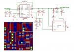
square buck-boost driver (TPS63020 and LT6106)
- Thread starter laserluke
- Start date


AnthoT
0
- Joined
- Jan 14, 2012
- Messages
- 2,133
- Points
- 48
Looks great! ")
Size is pretty awesome for such a powerful driver also, looks like all components are on one side, I know the bottom is the ground but maybe oh can get it even tinier by putting a few components on the bottom
By just getting the Pot & inductor underneath you'll have a micro sized 2Amp + buck boost :beer:
- Joined
- Mar 18, 2012
- Messages
- 173
- Points
- 0
Looks great!
Size is pretty awesome for such a powerful driver also, looks like all components are on one side, I know the bottom is the ground but maybe oh can get it even tinier by putting a few components on the bottom
By just getting the Pot & inductor underneath you'll have a micro sized 2Amp + buck boost :beer:
Thanks
With components on both sides, the problem become the heat dissipation because you need a good thermal contact between TPS63020, the inductor and the heatsink...
Last edited:
AnthoT
0
- Joined
- Jan 14, 2012
- Messages
- 2,133
- Points
- 48
Thanks
With components on both sides, the problem become the heat dissipation because you need a good thermal contact between TPS63020 and the heatsink...
yeah, well i was thinking if you did put them on both sides then you could really have the best driver at the moment, its already awesome & weve seen that already with your 17mm version :beer:
cant we just heatsink the TPS63020 directly, not through the board. i think its worth a shot to see just how tiny this thing can get
do you have the eagle files, i would be willing to edit them right now to try and make it as small as i can then ill post back the gerbers & hopefully dont wreck anything :crackup:
- Joined
- Mar 18, 2012
- Messages
- 173
- Points
- 0
yeah, well i was thinking if you did put them on both sides then you could really have the best driver at the moment, its already awesome & weve seen that already with your 17mm version :beer:
cant we just heatsink the TPS63020 directly, not through the board. i think its worth a shot to see just how tiny this thing can get
do you have the eagle files, i would be willing to edit them right now to try and make it as small as i can then ill post back the gerbers & hopefully dont wreck anything :crackup:
The TPS63020 thermal pads are located below the package. You have a very poor thermal contact (and a bad working driver...) if you place an heatsink above the plastic package.
Last edited:
AnthoT
0
- Joined
- Jan 14, 2012
- Messages
- 2,133
- Points
- 48
The TPS63020 thermal pads are located below the package. You have a very poor thermal contact (and a bad working driver...) if you place an heatsink above the plastic package.
Yeah that makes more sense...
Still a great driver though :beer:
foulmist
0
- Joined
- Mar 29, 2011
- Messages
- 1,056
- Points
- 48
Great, I was thinking of making it double sided but I am not sure of the heatsinking issue.
Perhaps I will give it a shot when I can order some proto boards. I am really tired of making my own etching. It's a pain for double sided
Perhaps I will give it a shot when I can order some proto boards. I am really tired of making my own etching. It's a pain for double sided
- Joined
- Mar 18, 2012
- Messages
- 173
- Points
- 0
Great, I was thinking of making it double sided but I am not sure of the heatsinking issue.
There is a simple solution for this doubt. Place a thermometer in good contact with the central via below the TPS63020, set the current to the desired value (1.8A or more) and measure the final temperature at the equilibrium.
The junction-to-board thermal resistance of the TPS63020 is 17°C/W so the junction temperature will be 17°C higher than your measure.
The absolute maximum temperature permitted for the junction is 150°C and the TPS63020 internal protection is programmed at 140°C so, at this temperature threshold, the IC stops operating.
Note for AnthoT: the junction-to-top-case thermal resistance of the TPS63020 is 47°C/W while the junction-to-bottom-case is 3.6°C/W !!! (place an heatsink on the top of the package is not a good idea...)
Last edited:
sinner
0
- Joined
- Oct 27, 2011
- Messages
- 2,565
- Points
- 83
Looks very good, its just great to have so many drivers coming up like that, i remember not so long ago we wondered if we will ever have our own boosts like the flex v5 now guess what this is much better and is much more capable 2A :beer:
+1 to you
+1 to you
AnthoT
0
- Joined
- Jan 14, 2012
- Messages
- 2,133
- Points
- 48
Yeah Luke that makes sense :beer:
foulmist
0
- Joined
- Mar 29, 2011
- Messages
- 1,056
- Points
- 48
So, is it possible to pwm these drivers? I read the ic has a set internal pwm at like 2.4mHz? Would that mean no? I would just like the most control over these as possible.
you can in several ways..
easiest - through the enable pin you have a miximum of around ~530Hz frequency. Any higher than that would be a constant on.
you can use a pwm signal like in my build I made to control the brightness
HERE
best way would be to PMW the output but that would need some changes to the board and additional components. Then you can have higher frequencies to modulate the output.
Last edited:
bobhaha
0
- Joined
- May 31, 2009
- Messages
- 3,239
- Points
- 63
WOW! I was working on a driver using the same IC and current sense amp!
Mine was gonna be double sided though...


PM coming...
Mine was gonna be double sided though...
PM coming...
foulmist
0
- Joined
- Mar 29, 2011
- Messages
- 1,056
- Points
- 48
haha I have a double sided design too still to be tested though!
still to be tested though! gillza
0
- Joined
- Jul 26, 2010
- Messages
- 583
- Points
- 28
if your designs are very similar to OP's why not post them here for everyone's benefit?
