IsaacT
0
- Joined
- Aug 25, 2010
- Messages
- 5,947
- Points
- 83
Name: LAYLA
Birthday: June 6th, 2013
This is to be the build thread for the Single Mode 638nm Laser I built tonight. I am dubbing her Layla, which is quite the name to live up to, but I think she will manage.
As always, I like to start about by giving you a list of the parts and an idea of the cost you could expect to build one of these yourself.
THE PARTS!!!
Parts List:
1 x Aurora SS Host
1 x Gold Plated, Copper Heatsink
1 x 638nm Single Mode Opnext Diode
1 x X-Drive V6 @ 290mA
1 x Focus Adapter
I purchased the Aurora as a flashlight with the heatsink and focus adapter from Cheech226 for 30 dollars. The Diode was purchased from DTR in a module with a glass lens for 45 Dollars(2 x @ 90 Dollars total). The driver was purchased from Clif at Cajunlasers preset to 290mA for 20 dollars.
Thus, the total spent was: 30+45+20=95 Dollars! I would say that that is a FANTASTIC deal on parts and for a DIYer, this is a great laser you can build for not too much money(when did 100 dollars become a small amount to me? I have been in this hobby for too long already :crackup: ).
THE BUILD PROCESS!!!
First, lets take a gander at the parts....yes, I realize I used the word gander
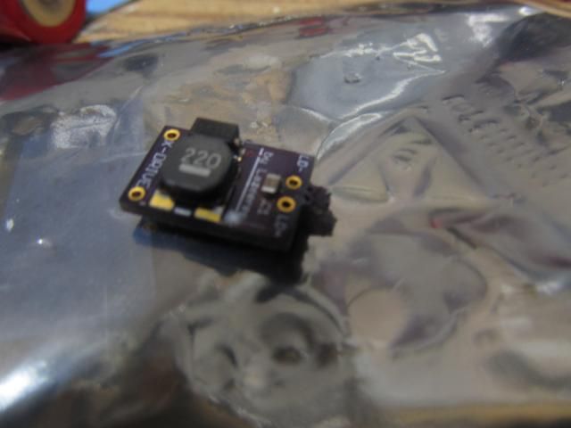
The driver:
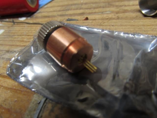
The Diode:
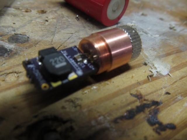
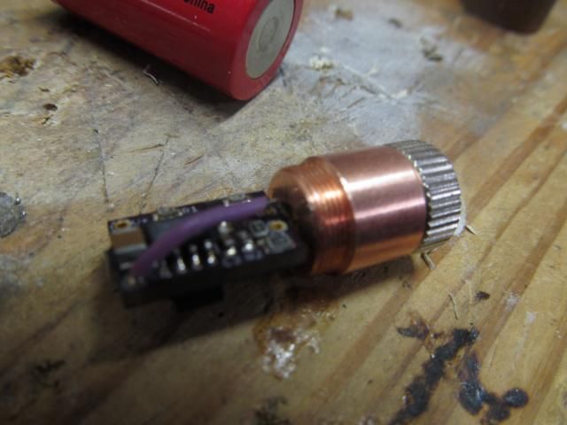
Second, I had to clip the diode pins and then attach the driver to the diode pins. I drilled out the pill for this build, so I had the option of either letting the driver sit down in the pill and attach leads to and from the diode, or just solder the driver directly to the diode. Since it makes the diode and driver one little unit, I chose to solder directly to the diode.
This was a little challenging, and actually the first time I have managed to solder a driver directly to a diode without problems. After googling how to read diode circuit schematics, I interpreted the Spec Sheet from Opnext(available from DTR's site) and figured out which pins were which. Then, I pre-tinned the solder pads for the diode pins as well as pre-tinning the diode pins themselves. I then lined up the driver and diode and carefully pressed the tip of my iron to the first joint. Once the first joint was made, it was easier to get the second because the assembly didn't want to go there separate ways anymore. :yh:
With the driver now very well attached to the diode, I pondered my options with regard to host connection input for the driver. I could either:
1. Solder a wire from the case pin to the driver, or
2. Solder a wire from the driver to a spot on the contact board in the pill.
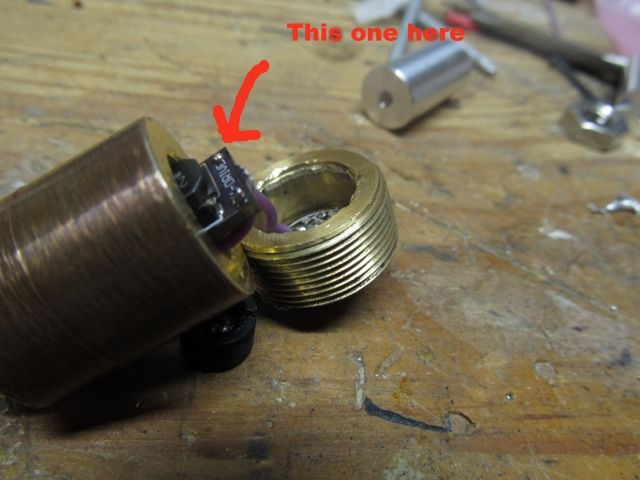
In the end I chose option 1, although due to the smaller size of these 3.8mm diodes, it was a little more difficult to do. In the end I think it turned out really well! I managed to trim some Flaminpyro Wire(the greatest stuff on earth!) down to the perfect length and solder the wire on the side of the pin facing away from the driver to prevent any shorts.
With all that done, I admired my handiwork and saw that it was good I then finished putting the pill back together, and then trimmed the wire coming from the contact board down to a more usable length(roughly an inch, maybe a little longer). I then tinned that wire and pushed it through the hole in the +input pad. And then I made probably the best solder joint of my life. It is pretty, lustrous, and perfectly round. I am proud of this solder joint more than one might deem appropriate :na: The photo doesn't do it much justice...but trust me when I say I felt like a pro after it.
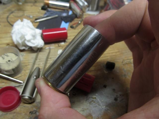
Then of course the difficult part of these builds is screwing the heatsink and pill in together so they don't twist any wires. The first time I started to screw it in, I encountered some resistance. It turns out some solder got on the side of the pill, making it difficult to screw in. So I unscrewed it and clipped that bit off. Here is how I screw them in: I pinch the Heatsink and the pill together using my index finger and thumb. I then use the other hand to screw the head of the laser onto the Heatsink/Pill assembly. Removing the lens makes for better traction, and always remember to go slowly. It is not a race.....unless it is a race.....in which case speed up with discretion since careless rabbits lose the race because they had to buy new parts while the turtle didn't maim his and finished whilst the rabbit still awaited USPS.
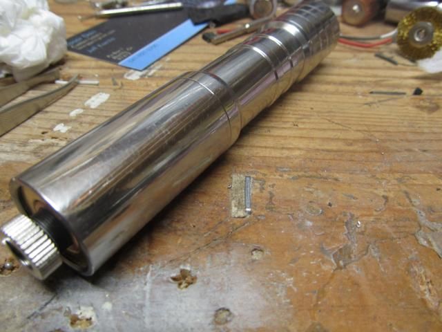
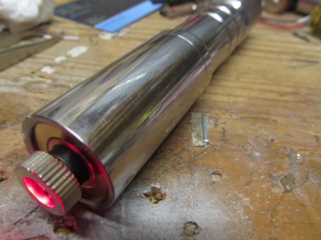
THE LASER!!!
This turtle very carefully finished his laser and tested it out with some 18350 Li-Ion Batteries he had handy and a Glass Lens.
The next step in any build, when possible, is to:
PLAY WITH IT!!!!
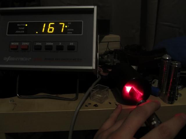
After that, of course, one will wish to take LPM measurements using his/her SUPER AWESOME ACCURATE LABORATORY LOOKING LASERPOWER METER!!!!! It is an official title for LPM's that make your room look like a science lab. On my SAALL-LPM, this laser outputs about 160mW on average:
And of course once you have metered your laser to your heart's content, you must return to the playing with it part! But maybe with a camera, like I did!
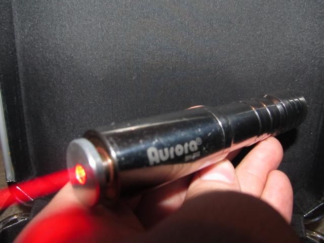
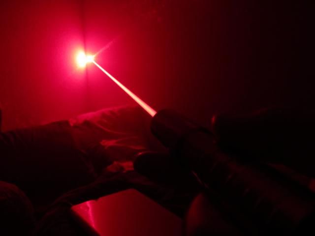
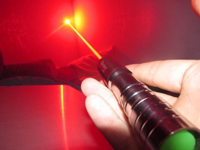
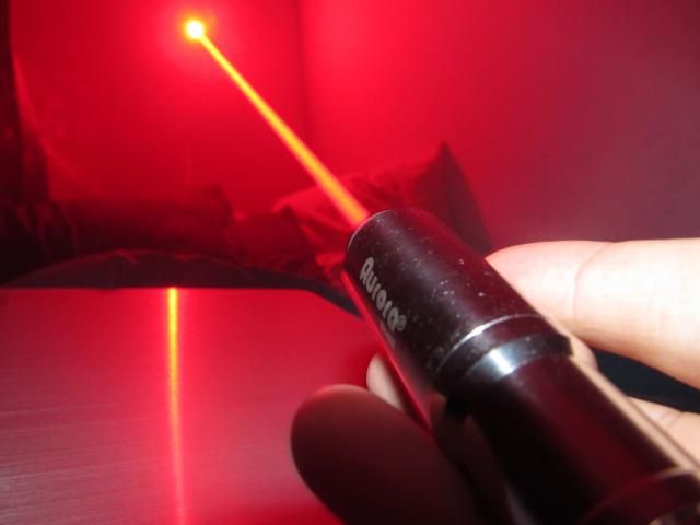
BEAMSHOTS!!!!
Okay, these first ones show it to be more red than it is in real life, but I like them and this is my thread so :na:
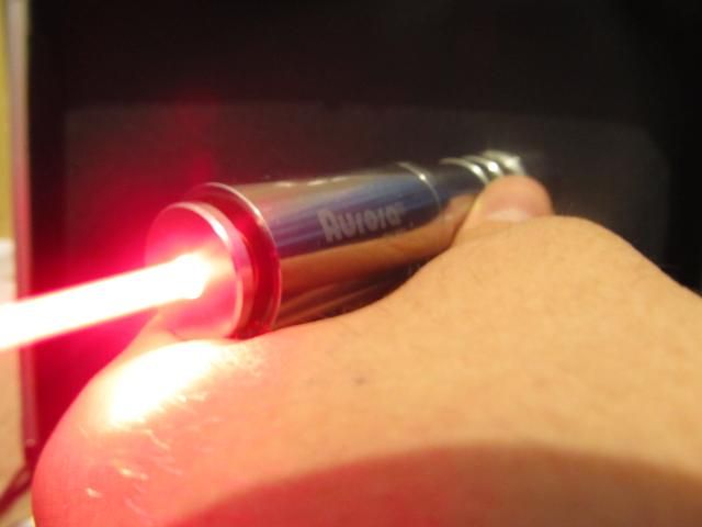
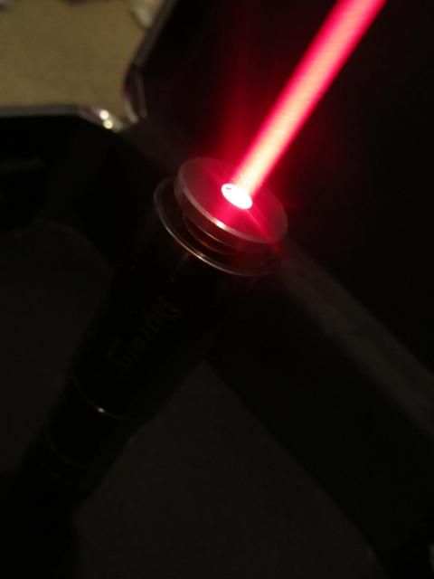
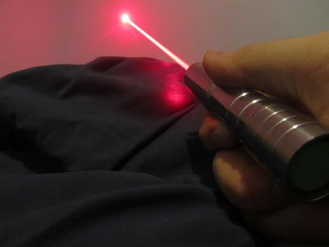
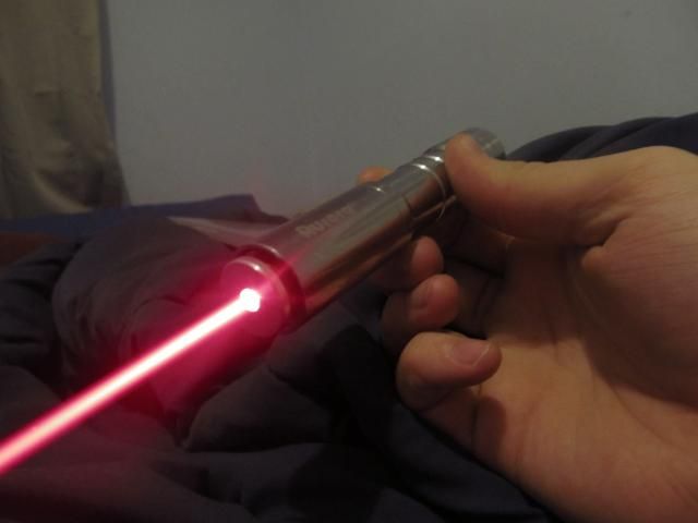
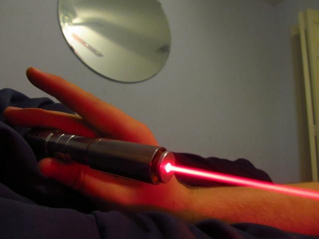
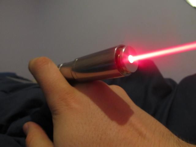
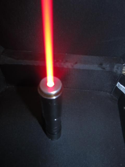
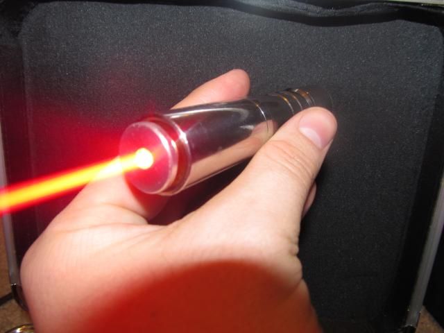
NOW FOR MORE COLOR APPROPRIATE BEAMSHOTS!!!!
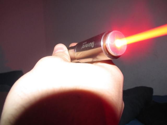
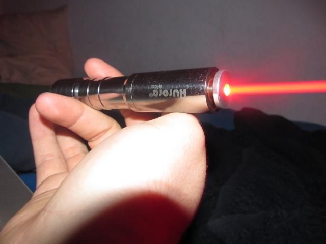
NOW FOR SOME VIDEO!!!
-Coming Soon!
CONCLUSIONS!!!!
Well, I hope some of you actually read down this far, if you have, you are a champ! I really like this laser, and it is a much prettier beam profile than the multimode 638nm. I am going to be getting a video made shortly, and after I upload it, I will embed it here for all to see. i am also considering having the tailcap changed to be a metal clicky cover.
Thanks for reading,
Isaac
Birthday: June 6th, 2013
This is to be the build thread for the Single Mode 638nm Laser I built tonight. I am dubbing her Layla, which is quite the name to live up to, but I think she will manage.
As always, I like to start about by giving you a list of the parts and an idea of the cost you could expect to build one of these yourself.
THE PARTS!!!
Parts List:
1 x Aurora SS Host
1 x Gold Plated, Copper Heatsink
1 x 638nm Single Mode Opnext Diode
1 x X-Drive V6 @ 290mA
1 x Focus Adapter
I purchased the Aurora as a flashlight with the heatsink and focus adapter from Cheech226 for 30 dollars. The Diode was purchased from DTR in a module with a glass lens for 45 Dollars(2 x @ 90 Dollars total). The driver was purchased from Clif at Cajunlasers preset to 290mA for 20 dollars.
Thus, the total spent was: 30+45+20=95 Dollars! I would say that that is a FANTASTIC deal on parts and for a DIYer, this is a great laser you can build for not too much money(when did 100 dollars become a small amount to me? I have been in this hobby for too long already :crackup: ).
THE BUILD PROCESS!!!
First, lets take a gander at the parts....yes, I realize I used the word gander
The driver:

The Diode:

Second, I had to clip the diode pins and then attach the driver to the diode pins. I drilled out the pill for this build, so I had the option of either letting the driver sit down in the pill and attach leads to and from the diode, or just solder the driver directly to the diode. Since it makes the diode and driver one little unit, I chose to solder directly to the diode.
This was a little challenging, and actually the first time I have managed to solder a driver directly to a diode without problems. After googling how to read diode circuit schematics, I interpreted the Spec Sheet from Opnext(available from DTR's site) and figured out which pins were which. Then, I pre-tinned the solder pads for the diode pins as well as pre-tinning the diode pins themselves. I then lined up the driver and diode and carefully pressed the tip of my iron to the first joint. Once the first joint was made, it was easier to get the second because the assembly didn't want to go there separate ways anymore. :yh:

With the driver now very well attached to the diode, I pondered my options with regard to host connection input for the driver. I could either:
1. Solder a wire from the case pin to the driver, or
2. Solder a wire from the driver to a spot on the contact board in the pill.
In the end I chose option 1, although due to the smaller size of these 3.8mm diodes, it was a little more difficult to do. In the end I think it turned out really well! I managed to trim some Flaminpyro Wire(the greatest stuff on earth!) down to the perfect length and solder the wire on the side of the pin facing away from the driver to prevent any shorts.

With all that done, I admired my handiwork and saw that it was good
I then finished putting the pill back together, and then trimmed the wire coming from the contact board down to a more usable length(roughly an inch, maybe a little longer). I then tinned that wire and pushed it through the hole in the +input pad. And then I made probably the best solder joint of my life. It is pretty, lustrous, and perfectly round. I am proud of this solder joint more than one might deem appropriate :na: The photo doesn't do it much justice...but trust me when I say I felt like a pro after it.
Then of course the difficult part of these builds is screwing the heatsink and pill in together so they don't twist any wires. The first time I started to screw it in, I encountered some resistance. It turns out some solder got on the side of the pill, making it difficult to screw in. So I unscrewed it and clipped that bit off. Here is how I screw them in: I pinch the Heatsink and the pill together using my index finger and thumb. I then use the other hand to screw the head of the laser onto the Heatsink/Pill assembly. Removing the lens makes for better traction, and always remember to go slowly. It is not a race.....unless it is a race.....in which case speed up with discretion since careless rabbits lose the race because they had to buy new parts while the turtle didn't maim his and finished whilst the rabbit still awaited USPS.

THE LASER!!!
This turtle very carefully finished his laser and tested it out with some 18350 Li-Ion Batteries he had handy and a Glass Lens.


The next step in any build, when possible, is to:
PLAY WITH IT!!!!
After that, of course, one will wish to take LPM measurements using his/her SUPER AWESOME ACCURATE LABORATORY LOOKING LASERPOWER METER!!!!! It is an official title for LPM's that make your room look like a science lab. On my SAALL-LPM, this laser outputs about 160mW on average:

And of course once you have metered your laser to your heart's content, you must return to the playing with it part! But maybe with a camera, like I did!
BEAMSHOTS!!!!
Okay, these first ones show it to be more red than it is in real life, but I like them and this is my thread so :na:


NOW FOR MORE COLOR APPROPRIATE BEAMSHOTS!!!!


NOW FOR SOME VIDEO!!!
-Coming Soon!
CONCLUSIONS!!!!
Well, I hope some of you actually read down this far, if you have, you are a champ! I really like this laser, and it is a much prettier beam profile than the multimode 638nm. I am going to be getting a video made shortly, and after I upload it, I will embed it here for all to see. i am also considering having the tailcap changed to be a metal clicky cover.
Thanks for reading,
Isaac