Welcome to Laser Pointer Forums - discuss green laser pointers, blue laser pointers, and all types of lasers

LPF Donation via Stripe | LPF Donation - Other Methods

Links below open in new window

ArcticMyst Security by Avery

Simple music visualizer / laser oscilloscope

Joined
Apr 4, 2010
Messages
7
Points
3
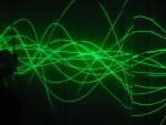
I wanted something more linked to the actual music than the mirror-shaker visualizer, and what's better than an oscilloscope for displaying AC signals?

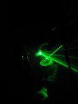
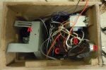
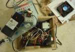
My dad happened to have a motor with a hexagonal mirror for barcode scanning which I used for the horizontal scanning. Unfortunately I couldn't get that motor to turn slowly enough so I had to put the mirror onto a gearmotor. It has something like a 120 degree scan, so the resulting projection is huge even at 10' away from the wall.

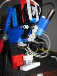
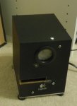
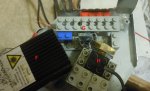
The vertical scanning is accomplished with a tiny homemade speaker that drives a mirror rather than a cone. In the picture this is the cylinder at the bottom. It's just a spool-shaped piece of plastic wrapped with magnet wire. The mirror is glued to a magnet that sticks to another magnet on the other side of the latex suspension. This little speaker produces almost no sound and moves the mirror fairly straight up and down. I drive it with a little of the power from my subwoofer amp.

The remainder of the setup is just alignment. I used legos to make prototyping easier. It's important that the scanning mirror be as close as possible to the speaker mirror to reduce clipping of the projection for high amplitudes. The laser strikes the speaker mirror first.

I'm still waiting for my 50mw labby to come in from Aixiz but you guys can still get the idea with my 5mw installed. The pictures include multiple passes of the scope due to the exposure length. I'll have to wait until I have my 50mw laser to do video since my webcam can't capture very well in darkness. I can't wait for that 10x increase in power! :)
 

Attachments

  • IMG_4894-small.jpg
    IMG_4894-small.jpg
    187.4 KB · Views: 18,239
  • IMG_4937-small.jpg
    IMG_4937-small.jpg
    135.1 KB · Views: 967
  • IMG_4888-small.jpg
    IMG_4888-small.jpg
    56.3 KB · Views: 936


Joined
Jan 7, 2007
Messages
6,309
Points
83
Just a thought...... Those sleds are designed to move that tiny lens. Adding the mass of a large, thick mirror will dampen the ability of that "motor" to react to input in speed and angular throw.
You might try smaller, thinner or lighter mirrors.

HMike
 
Joined
Apr 4, 2010
Messages
7
Points
3
Version 3.0

I created a better version with my 50mw laser a while ago, and recently I made some changes to make it more portable.

The original Y scanner wasn't very good since it jiggled the mirror a lot rather than just changing the angle along one axis. I hacked some components from a CD burner together with a mirror to create a new Y axis.

The first two versions used the output of the amp for my subwoofer to drive the Y axis. It worked fine but it wasn't very portable like that. I disassembled a set of Logitech computer speakers to use the tiny amp in the bass speaker, and while I was at it I decided to cram the entire apparatus inside of it! Now it's all packaged up into one little box that just requires an outlet and audio from a computer or MP3 player, and the output is better than anything I've ever seen at a club. :D

After I got the o-scope working with the new laser in version 2.0 I tried it out in fog to see the entire undulating sheet rather than just what was projected on the wall. It's really incredible to see the amplitude of the music playing in 3D over your head in brilliant green light... the pictures don't do the effect justice.

It still needs some exterior work to make it look nicer, but it runs great and it looks good enough for my brother's upcoming birthday party as-is if I don't get around to painting it before then. :beer: :bday:

If anyone is interested enough to want details on the build let me know and I'll try to put together a little walkthrough of the design.
 

Attachments

  • laserosc-crop.JPG
    laserosc-crop.JPG
    59.7 KB · Views: 491
  • scan 1 small.JPG
    scan 1 small.JPG
    109.1 KB · Views: 469
  • scan 2 small.JPG
    scan 2 small.JPG
    99.9 KB · Views: 823
  • scan 3 small.JPG
    scan 3 small.JPG
    97.9 KB · Views: 2,543
Joined
Feb 12, 2010
Messages
129
Points
0
great DIY build i think this is right up my alley because i know i have all of these parts laying around my house. id love a few more details on your build. also do you have a video of the oscilloscope in action?
 
Joined
Apr 4, 2010
Messages
7
Points
3
:thanks:

I don't have a video yet, but I'll give it a shot. I'll work on a post detailing the design sometime this week. I'm working all week so it might be a few days before I can find the time.
 
Joined
Feb 12, 2010
Messages
129
Points
0
sweet cant wait to see it in action and make one. when i get home from work im going to start tinkering around with stuff and see what i can come up with
 
Joined
Apr 4, 2010
Messages
7
Points
3
Video!

I made a video with my netbook's webcam. It gives you a bit of an idea of what it's like at least, but the quality isn't very good. Since I was using my netbook as both the music source and the recorder the audio got all screwed up when I had the speakers on, so even though you can hear the fog machine going off and the vertical mirror moving you can't hear the music. :(

There is some wobble in the scanning mirror right now so even when the music is quiet the laser will slowly travel up and down a few degrees. I hope to fix that using my dad's lathe. I'll plan on taking pictures of the internals when I take it apart to fix the mirror.
 

Attachments

  • Capture_20110215_5.wmv
    8 MB · Views: 123
Joined
Apr 4, 2010
Messages
7
Points
3
More detailed description

I've attached 3 pictures of the internals and labeled the important parts to make it easier to reference them. The view is from the bottom.

A: Optics piece - Holds the laser and mirrors. Removable as one piece for easy adjustment.
B: Original power supply and amp from the computer speakers - Used as it was with the exception of cutting off the speaker and using those leads to run the vertical mirror.
C: 12v "wall wart" - Runs the fan and the motor for the horizontal scan.
D: Potentiometer - Speed control for the horizontal scan motor.
E: Laser power supply
F: 50mw green laser
G: Vertical mirror
H: Horizontal scanning mirror


The amp power supply, laser power supply, and 12v power supply all share the same 110VAC cord. Everything has heat-shrink on it to avoid shorts.

The raw output for the speaker is used to run the vertical mirror, so it is AC. The vertical-mirror-moving-thingy (galvo seems like a strong word for it...) switches direction when the polarity switches, it moves in proportion to the amplitude of the input, and it returns to center when the input is 0. It's something I pulled out of a CD burner.

The horizontal mirror spins at a constant, fairly slow, speed. It's not actually getting 12v due to the potentiometer and the fact that the 12v supply is current limited to less than the motor and fan want to consume. I chose the lego motor because I had it laying around and it's a gear motor. Ungeared motors generally run too fast for this. The mirror itself is from a barcode scanner.

The hardest part of this build, assuming you already have the parts, is lining up the mirrors just right. The laser hits the vertical mirror first, which creates a beam that jiggles with the amplitude of the music. This jiggling beam is then scanned horizontally by the spinning mirror. Note that the amount of movement on the vertical axis is limited by the height of the scanning mirror and how close it is to the vertical mirror. The closer you can get them without touching the more the vertical mirror can move without throwing the beam off the scanning mirror and clipping off the tops of the waveforms.

I decided to start on the optical part by hot gluing lego pieces to the bottom of each part, then using more legos to get them to the right heights. Once I had them where I wanted them on the frame (which used to be a computer PSU case) I hot glued the lower lego pieces to it. When the hot glue cooled a bit I unsnapped the legos on the parts from the legos on the frame and secured them with more hot glue.

Most of the layout will depend on exactly which components you are using, but I think a removable optical frame is a must-have. Actually that frame is just my version 2.0 unit trimmed to be smaller and bent to have screw tabs, so it was working on its own before I even had the box.

Let me know if you have any questions!
 

Attachments

  • inside 1.jpg
    inside 1.jpg
    130.3 KB · Views: 600
  • inside 2.jpg
    inside 2.jpg
    159.9 KB · Views: 427
  • inside 3.jpg
    inside 3.jpg
    120.2 KB · Views: 505
Joined
May 4, 2009
Messages
5,443
Points
113
Good on you for making a new and different laser entainment device maby it's been done befor but I haven't seen it and I think you have do a fine job +1


Top