Welcome to Laser Pointer Forums - discuss green laser pointers, blue laser pointers, and all types of lasers

LPF Donation via Stripe | LPF Donation - Other Methods

Links below open in new window

ArcticMyst Security by Avery

Resources for designing constant current drivers

Joined
Dec 10, 2011
Messages
120
Points
18
Hello everyone,

I apologize if this is a search away, I've searched many times over the past while but haven't found much information, despite my expectations that I would.

I took a course on DC-DC switching converters, but never learned anything about making a constant current driver. I would like to be able to do this so I don't have to go searching forever for a driver suitable for whatever diode I'm buying, plus I can get some design experience. Can anyone point me to application circuits, references, design examples, etc.?

Thank you!


Joined
Feb 5, 2008
Messages
6,252
Points
83
Well basically it boils down to the knowledge of all the chips designed for constant current output that there currently are.

Once you know that, for example, LM1117 can be used for constant current driver, you look up it's data sheet to find out template schematics and it's properties.

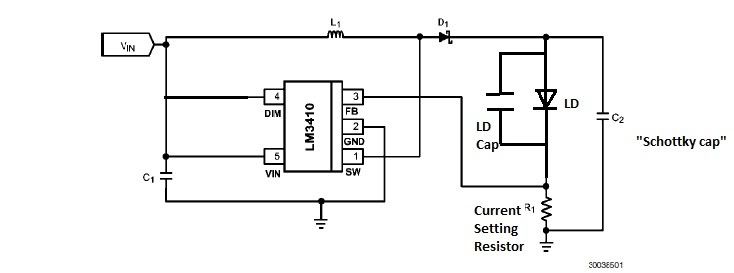
I have also built my own switching boost driver a while back using this chip:


To be honest, I don't quite remember how I came across that chip but after I find out, I got a few samples and tried out some boards, and it worked great.

So really it just comes down to searching which chips have the properties you need.
 
Joined
Dec 10, 2011
Messages
120
Points
18
Well basically it boils down to the knowledge of all the chips designed for constant current output that there currently are.

That's mainly what I'm looking for, I'd like to be able to design any driver I need (and leave any successful designs in the forums). I take it the "PMIC - LED drivers" section of the Digikey product index is a good place to start?
 

Hiemal

0
Joined
Dec 27, 2011
Messages
1,443
Points
63
You can technically turn any constant voltage driver into a constant current one using a few different techniques.

The LM3410 is *technically* a constant voltage regulator but the control scheme (the feedback point being set behind the resistor) is what allows it to be constant current. If you use that same exact method to any other voltage regulator it'll become constant current.

Though, the biggest drawback of doing this, is lack of common ground, and also the voltage across the resistor will be whatever your feedback voltage is. Most common is about 1.2-1.3 volts, so you'll ALWAYS be dropping 1.2-1.3 volts across your resistor.

At high currents that'll become a pretty significant amount of power lost.

So, what you do instead, is add another component, a high side current sense op amp.

ZXCT1109, ZXCT1009, LT6106 are some to name. Basically they amplify the voltage across the resistor and allows you to "high side sense", aka, you get to put the resistor BEFORE your load, allowing a common ground. Additionally, because you're amplifying the voltage across the resistor you also get to basically "choose" what voltage you're dropping. This can let you get as low as 50-100 mV of sense voltage, even with a feedback voltage of 1.25 volts.

Check out the datasheets for the high side sense op amps, they'll explain the process a lot more. Also, do read whatever IC you choose's datasheet very thoroughly. They'll sometimes have extra features or things added that can either be useful or detrimental to laser diode driving.

I'd go a lot more into it but that would take a LOT of writing, but this is a basic rundown for constant voltage to constant current changing.
 
Joined
Dec 10, 2011
Messages
120
Points
18
Awesome, that is exactly the kind of information I was looking for! You mention common ground as a good thing to have. Is that because usually in a handheld, the battery, driver, and diode "ground" are all electrically connected?
 
Joined
Feb 5, 2008
Messages
6,252
Points
83
Awesome, that is exactly the kind of information I was looking for! You mention common ground as a good thing to have. Is that because usually in a handheld, the battery, driver, and diode "ground" are all electrically connected?

Yes.

However if you have a case neutral diode, such as 445nm diodes, it doesn't matter since technically the laser diode isn't connected to the case at all.

I have frequently used case pin for negative driver input in blue builds.
 

Hiemal

0
Joined
Dec 27, 2011
Messages
1,443
Points
63
Kind of an interesting sidenote, I was looking at a microboost drive, and looked at the main IC....

The main IC is literally the LM3410, in a pinless package, with one of those high side op amps feeding its feedback pin.

Crazy.
 
Joined
Feb 5, 2008
Messages
6,252
Points
83
Kind of an interesting sidenote, I was looking at a microboost drive, and looked at the main IC....

The main IC is literally the LM3410, in a pinless package, with one of those high side op amps feeding its feedback pin.

Crazy.

No kidding?

Popular little chip. Pinless ones (aka BGA package) are impossible to solder conventionally, but I recommend getting the 5-pin ones like shown in my schematic.

It's been a long while since I put together a boost driver.

Then again I've been building very sparsely, anyway.

Still the homemade boost driver was one of the more fun projects. Development, testing, and finally usage in builds. Much learned :)


Top