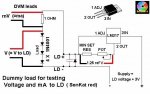
Just got my driver built (daedal) and built the dummy load (4diodesand 10hmres). Built just like the pics showed. My problem is that if you check the diodes and resistors you get nothing on the meter. But if you switch the polarity I get the proper measurements. Something isnt right. Or are you supposed to have reverse diodes. Help please. MIKE
LPF Donation via Stripe | LPF Donation - Other Methods
Links below open in new window
ArcticMyst Security by Avery


You are using an out of date browser. It may not display this or other websites correctly.
You should upgrade or use an alternative browser.
You should upgrade or use an alternative browser.
quick help with dummy load
- Thread starter madleds
- Start date


rog8811
0
- Joined
- Jul 24, 2007
- Messages
- 2,749
- Points
- 0
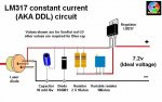
Diodes are a bit like one way valves, so everything is fine, if you have built the full DDL circuit you have a diode that will not conduct if the batteries are in correctly and the LD will light, if you put the batteries the wrong way round the power will flow through the diode and not the LD. The same applies to the dummy load, one way nothing happens, the other way current flows.
Regards rog8811
Regards rog8811
Attachments
as far as the polarity of the 47uf cap, is the longer leg the pos or neg? and for the in4001 diode the white strip on it? I put this together just like the pics but it doesnt respond the proper way. So I reversed the polarity of the dummy load and it worked as far as measuring the ma's and the volts. Then hooked up the ld and got a small amount of light. Not enough to shine 2 feet on the wall. So i shorted the cap and disconnected the ld and looked at the circuit again. Now i'm lost on what to do.
rog8811
0
- Joined
- Jul 24, 2007
- Messages
- 2,749
- Points
- 0
I have put the dummy load picture in my post above and the circuit diagram in this one...as far as I know they are correct, follow the stripes on the diodes.
Whether your cap is an electrolytic or a tant it should be marked for polarity. Neg is marked by stripe on electrolytics, + normaly printed on tant's.
I am not sure what you are saying here, could you post a photo of your setup? It may help with diagnosing the problem.
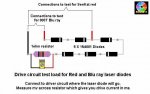
In the mean time, if you connect the dummy load as shown in the top drawing, (red to + black to -), put the meter, set to mv, across the resistor (wire colours not important) when you turn the pot does anything happen?
Regards rog8811
Whether your cap is an electrolytic or a tant it should be marked for polarity. Neg is marked by stripe on electrolytics, + normaly printed on tant's.
I put this together just like the pics but it doesnt respond the proper way.
I am not sure what you are saying here, could you post a photo of your setup? It may help with diagnosing the problem.
In the mean time, if you connect the dummy load as shown in the top drawing, (red to + black to -), put the meter, set to mv, across the resistor (wire colours not important) when you turn the pot does anything happen?
Regards rog8811
Attachments
rog8811
0
- Joined
- Jul 24, 2007
- Messages
- 2,749
- Points
- 0
- Joined
- Aug 1, 2008
- Messages
- 335
- Points
- 0
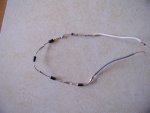
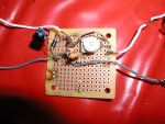
madleds said:here is the driver
i think your capacitors backwards... if that makes a difference
- Joined
- Sep 20, 2008
- Messages
- 17,622
- Points
- 113
madleds said:here is the driver
Your Capacitor is hooked up backwards... the white wire that goes to your Dummy Load
is Positive...

Jerry
rog8811
0
- Joined
- Jul 24, 2007
- Messages
- 2,749
- Points
- 0
Cap is backwards as photographed. Grey stripe is negative, other than that it looks fine (cannot be 100% sure as I am guessing that the LM317 is the right way round).
With the 2 resistors you will get about 2 ohms as the min resistance.
Your test load is correct as well....
Have you checked the ref voltage with the test load in place?
Regards rog8811
With the 2 resistors you will get about 2 ohms as the min resistance.
Your test load is correct as well....
Have you checked the ref voltage with the test load in place?
Regards rog8811
rog8811
0
- Joined
- Jul 24, 2007
- Messages
- 2,749
- Points
- 0
Voltage looks close for a red, what is your input voltage?
you should have a range from top of pot to bottom of pot in mv, can you post it? (top end should be around 625ma with that setup)
Regards rog8811
[edit]What red are you wanting to use with this?[/edit]
you should have a range from top of pot to bottom of pot in mv, can you post it? (top end should be around 625ma with that setup)
Regards rog8811
[edit]What red are you wanting to use with this?[/edit]
