- Joined
- Feb 1, 2012
- Messages
- 22
- Points
- 0
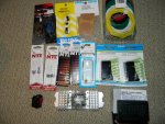
so Im in the process of making a LPM but there is something I dont understand...
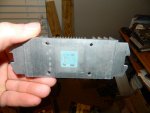
The type of LPM Im making uses a tec module on a heatsink but everyone seems to be using either a black heatsink or painting their heatsink black. Now I understand that the reason to paint the tec black is to absorb the light energy from the laser but correct me if Im wrong the heatsink is connected to the "cool side" of the tec.
In that case why would we want the heatsink absorbing light energy from the laser. I know the laser is focused on the tec but their is usually some type of light divergence outside of the beam.
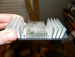
Wouldnt we get a quicker and/or more accurate reading if the heatsink only absorbs the energy from the tec? And in that case why wouldnt we just polish the face of the heatsink in order for it to reflect excess light energy outside the collumated beam?
Has anyone experimented with this or can anyone give me insight on this subject before I either polish my silver heatsink or etch it and anodize it black?
-Scott
The type of LPM Im making uses a tec module on a heatsink but everyone seems to be using either a black heatsink or painting their heatsink black. Now I understand that the reason to paint the tec black is to absorb the light energy from the laser but correct me if Im wrong the heatsink is connected to the "cool side" of the tec.
In that case why would we want the heatsink absorbing light energy from the laser. I know the laser is focused on the tec but their is usually some type of light divergence outside of the beam.
Wouldnt we get a quicker and/or more accurate reading if the heatsink only absorbs the energy from the tec? And in that case why wouldnt we just polish the face of the heatsink in order for it to reflect excess light energy outside the collumated beam?
Has anyone experimented with this or can anyone give me insight on this subject before I either polish my silver heatsink or etch it and anodize it black?
-Scott


 (unless someone else has already tried)