Welcome to Laser Pointer Forums - discuss green laser pointers, blue laser pointers, and all types of lasers

LPF Donation via Stripe | LPF Donation - Other Methods

Links below open in new window

ArcticMyst Security by Avery

Question about multimeter and driver perfomance

Joined
Oct 10, 2008
Messages
35
Points
0
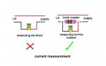
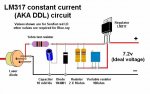
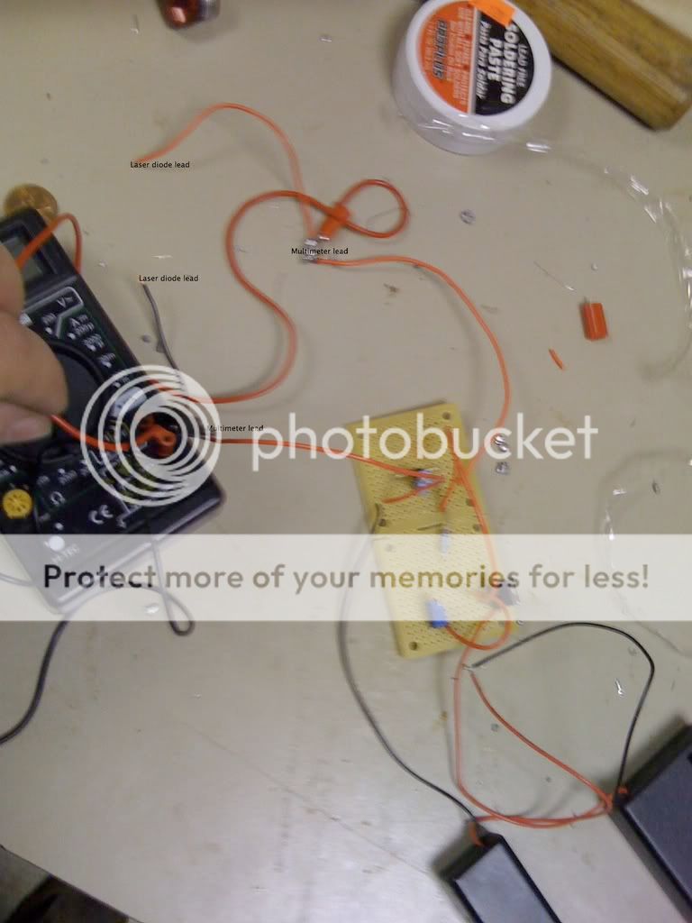
Right now I am currently using a daedal DDL driver for my SLD1239JL-54 16x DVD diode. I designed my driver so I could measure amperage while I run the laser diode. I did this by soldering the leads to a multimeter into the circuit like in this photo
IMG_0006texg.jpg

I currently have the driver set to 250 milliamps. Using 2 multimeters I noticed that whenever I connect the multimeter leads to the multimeter and set it to measure amperage, the current in the laser diode leads drop to  0.02 volts and 110 milliamps. If there was already a laser diode on the diode leads, Will this drop in current resulting from connecting the multimeter leads or sudden rebound in current after disconnecting the multimeter leads harm the laser diode? If so, how should I change the circuit so I can measure and/or disconnect my multimeter without frying the diode?


Joined
Jul 24, 2007
Messages
2,749
Points
0
Re: Question about multimeter and driver perfomanc

If you put a 1ohm resistor in the 2 holes in the breadboard where the probe leads are meant to go, set your meter to mv and measure the volts across the resistor mv will be equal to ma to the LD.

Don't forget, with the supply off, short out the capacitor before you mod the circuit.


Regards rog8811
[edit]Just noticed, I think you had the meter wired in wrongly, it should complete the circuit not go across it.[/edit]
 

Attachments

  • measure_ma_01.jpg
    measure_ma_01.jpg
    27.6 KB · Views: 2,339
Joined
Dec 20, 2007
Messages
31
Points
0
Re: Question about multimeter and driver perfomanc

why is not good to measure ma direct??
because of mistake of m-metar or what??
tnx
 
Joined
Jul 24, 2007
Messages
2,749
Points
0
Re: Question about multimeter and driver perfomanc

Using the meter as part of the circuit (measuring ma direct) it is easy, when removing the meter to use elsewhere and reconnecting the LD, to forget to discharge the capacitor.
With the resistor in circuit you can connect to it at any time without having to worry about doing any damage.

At the end of the day the choice is yours, but you need to check how you have the meter connected in your photo, it is hard to be sure but it looks wrong.

Regards rog8811
 
Joined
Dec 20, 2007
Messages
31
Points
0
Re: Question about multimeter and driver perfomanc

oke tnx a lot on your response........
btw no worry for capacitor it is connected directly to diode because i killed once one by forgetting to discharge it.......

Mario
 
Joined
Feb 21, 2008
Messages
1,056
Points
0
Re: Question about multimeter and driver perfomanc

I also tend to attach my output cap to the diode. I also put a resistor (maybe 470 ohms) across the capacitor to discharge it the moment power is interrupted for any reason. This resistor is an even better idea if your capacitor is on the driver board, and you like to connect different diodes up for testing. Adding this resistor can be a little life insurance for diodes.
 
Joined
Oct 10, 2008
Messages
35
Points
0
Re: Question about multimeter and driver perfomanc

billg519 said:
I also tend to attach my output cap to the diode. I also put a resistor (maybe 470 ohms) across the capacitor to discharge it the moment power is interrupted for any reason. This resistor is an even better idea if your capacitor is on the driver board, and you like to connect different diodes up for testing. Adding this resistor can be a little life insurance for diodes.


Are you saying to put a 470 ohm resistor were I already have the capacitor or are you saying to get another capacitor? If so, what type of capacitor and how many microfaurads should it be? Would doing this allow me to measure amperage directly while my laser and driver is running without ruining the laser?

If you put a 1ohm resistor in the 2 holes in the breadboard where the probe leads are meant to go, set your meter to mv and measure the volts across the resistor mv will be equal to ma to the LD.
I don't know which two holes you are talking about, are you talking about the holes were the wires connecting to the multimeter leads are? Also when your saying supply are you saying put both the positive and negative leads of the supply on one side of the resistor and put both the positive and negitive leads on for the diode on the other side of the resistor? If that is so, how do you I allow the proper polarity to go to the proper pins on the diode?


 Feel free to copy, edit, label, or draw on my posted photo to help explain your responses. Thanks
 
Joined
Dec 20, 2007
Messages
31
Points
0
Re: Question about multimeter and driver perfomanc

if im right this is picture from rog8811 who has written very good post about dummy load and how to check and prepare driver for LD im sorry but i couldn't find the link but i have saved all to comp
here is just a picture......that my help you.................this helped me a lot....... tnx rog8811


i hope this will help you

Mario
 
Joined
Oct 10, 2008
Messages
35
Points
0
Re: Question about multimeter and driver perfomanc

Mario said:
if im right this is picture from rog8811 who has written very good post about dummy load and how to check and prepare driver for LD im sorry but i couldn't find the link but i have saved all to comp
here is just a picture......that my help you.................this helped me a lot....... tnx rog8811


i hope this will help you

Mario

Your picture is very helpful, it's now clear on were to put the resistor. Just my only question are should I ignore the part that says to put the 4 1n diodes if I don't want to measure voltage? Also another thing I just want to let you know, is that my driver uses 6 volts instead of 3 volts and has a 1N diode after the capacitor rather then before it. Hopefully those things won't make a difference but if it does be sure to let me know. Thanks.

Please be sure to comment about my response to billg's idea and whether or not it would allow me to measure amperage and voltage directly and if it requires another capacitor
 
Joined
Jul 24, 2007
Messages
2,749
Points
0
Re: Question about multimeter and driver perfomanc

I don't know which two holes you are talking about,are you talking about the holes were the wires connecting to the multimeter leads are?
As I am unsure your meter is correctly connected do it this way, take the neg line straight through to the LD, put the resistor into the line from the output of the regulator to the LD, see drawing below, the resistor can be either side of the cap and 1n4001 diode.

Regards rog8811
 

Attachments

  • LM317_components_with_test_res01.jpg
    LM317_components_with_test_res01.jpg
    45.1 KB · Views: 1,222
Joined
Oct 10, 2008
Messages
35
Points
0
Re: Question about multimeter and driver perfomanc

rog8811 said:
I don't know which two holes you are talking about,are you talking about the holes were the wires connecting to the multimeter leads are?
As I am unsure your meter is correctly connected do it this way, take the neg line straight through to the LD, put the resistor into the line from the output of the regulator to the LD, see drawing below, the resistor can be either side of the cap and 1n4001 diode.

Regards rog8811
 

Thank you
 
Joined
Feb 21, 2008
Messages
1,056
Points
0
Re: Question about multimeter and driver perfomanc

Referring to rog8811's diagram above, the resistor (470 ohms) that I proposed, would be connected across the 10uf 16v capacitor, so the cap is always discharged when power goes off. This resistor only serves to drain the cap. It has no use whatsoever for current measurement.
 
Joined
Oct 10, 2008
Messages
35
Points
0
Re: Question about multimeter and driver perfomanc

billg519 said:
Referring to rog8811's diagram above, the resistor (470 ohms) that I proposed, would be connected across the 10uf 16v capacitor, so the cap is always discharged when power goes off. This resistor only serves to drain the cap. It has no use whatsoever  for current measurement.

So your saying that without a 470 ohm resistor, just turning the switch to the off position and turning it back on would fry a diode?! If that was so, then why was it not mentioned in daedals driver forum?
 
Joined
Jul 24, 2007
Messages
2,749
Points
0
Re: Question about multimeter and driver perfomanc

So your saying that without a 470 ohm resistor, just turning the switch to the off position and turning it back on would fry a diode?! If that was so, then why was it not mentioned in daedals driver forum?
As you have stated that your capacitor is connected straight onto the LD pins you do not need to worry about the discharge resistor as any disconnections you make will be down side of it.

Even so I would always go the 1ohm sense resistor for current measurement route as it is so convenient.

Regards rog8811
 
Joined
Oct 10, 2008
Messages
35
Points
0
Re: Question about multimeter and driver perfomanc

rog8811 said:
As you have stated that your capacitor is connected straight onto the LD pins you do not need to worry about the discharge resistor as any disconnections you make will be down side of it.

Even so I would always go the 1ohm sense resistor for current measurement route as it is so convenient.

Regards rog8811

Does the fact that I use a 47 uF 35 volt capacitor instead of a 10 uF 16v make a difference?
 
Joined
Jul 24, 2007
Messages
2,749
Points
0
Re: Question about multimeter and driver perfomanc

Does the fact that I use a 47 uF 35 volt capacitor instead of a 10 uF 16v make a difference?

It is probably a little large but not a problem, it will do the job just the same.

Regards rog8811


Top