djQUAN
0
- Joined
- May 27, 2013
- Messages
- 1,154
- Points
- 63
I just received my i4 today from Fasttech and a quick check and it seems to work except that when charging a battery on slot 2, the LEDs for it light up along with the LEDs for slot 4 even when there's only one battery.
I didn't want to wait for shipping back and wait for another and was also curious to see what's inside the i4 so I took the screwdriver out. warranty? what warranty? :shhh:
I'm not going to do a detailed review of the i4 as there already exists a very detailed i4 review with graphs and measurements but was missing some internal pictures so I took mine apart.
Here are some pictures that I took...
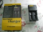
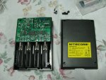
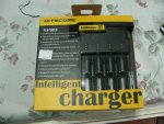
Package as received:

What?

four screws are hidden under the foam rubber feet. Pry out with a tweezer to gain access to the screws.

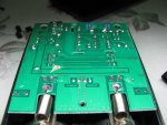
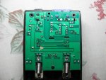
bottom of the PCB. Soldering could have been cleaner but it cost only $20. IPA and a toothbrush should clean it up nicely. It does have the essential isolating slots separating the live circuitry directly connected to the mains to have enough safety clearance to prevent electrocution. The PCB is also a nice FR4 substrate rather than the cheap paper phenolic material.

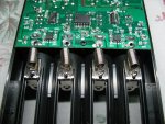
springs for battery contacts are soldered on both ends which allows more reliable electrical connection - I haven't seen it done in cheap chargers before:

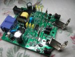
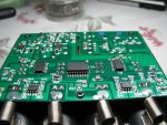
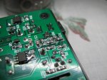
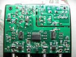
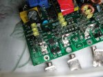
top of the main PCB. On the top left are the AC to DC converter. Top right appears to be the two buck converters that steps down the voltage to charge the batteries. Bottom part controls switching of the two charger channels to four battery slots.

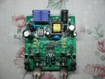
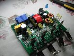
angled view of the board. The switching controller for the AC-DC converter is a VIPer22A device with voltage feedback using a TL431 and optocoupler which is loads better than a self oscillating transistor switcher in cheap chargers.

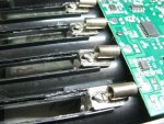
controllers that route power from two charger channels to four battery slots are controlled by what appears to be dual mosfet devices on both the positive and negative battery lines.

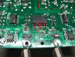
Now there's your problem: I found two shorts on the main controller IC which might be causing my problem but I won't touch it now. I don't have access to my soldering station so it'll have to wait. I'll post again when I've cleaned up the solder joints.

edit: couldn't wait to see if the solder bridges were causing the trouble or not so I used a knife to cut the solder bridges out. Charger works perfectly now.") I'll still tear it apart again to clean up the solder blobs and flux residue though.
I'll still tear it apart again to clean up the solder blobs and flux residue though.
edit 2 (2013/06/24)
I convinced my uncle to buy an i2 and it just arrived. What better way to christen it than do another teardown. :na:
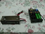
Package contains the charger itself, a power cord and manual.

Same way of opening as the i4. screws are hidden under the foam rubber feet. Once the bottom cover is out, this is what we get. You can clearly see the nice clearance gap separating the live circuitry directly connected to the mains and the DC output which you will come on contact to when inserting batteries.

Soldering looks much cleaner than my i4. There's just an odd solder ball on the bottom right of the pic and a piece of tape which were both easily removed with a fingernail.

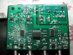
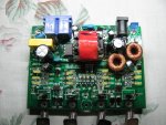
Top of the board. Top half is the main AC-DC power supply which used the same VIPer22A device but with a smaller transformer (yellow/black square part). The buck converters are on the bottom left and right corners using drum core inductors (the i4 used toroidals) and the main controller IC is the one in the middle.

Another view in an angle.

You don't usually get these in cheap chargers. Mains input is fused and an NTC thermistor to limit inrush current.

All in all, I think these chargers are a nice decent design especially considering the price. If you don't have a decent charger, I highly recommend you get one. :beer:
I didn't want to wait for shipping back and wait for another and was also curious to see what's inside the i4 so I took the screwdriver out. warranty? what warranty? :shhh:
I'm not going to do a detailed review of the i4 as there already exists a very detailed i4 review with graphs and measurements but was missing some internal pictures so I took mine apart.
Here are some pictures that I took...
Package as received:
What?
four screws are hidden under the foam rubber feet. Pry out with a tweezer to gain access to the screws.
bottom of the PCB. Soldering could have been cleaner but it cost only $20. IPA and a toothbrush should clean it up nicely. It does have the essential isolating slots separating the live circuitry directly connected to the mains to have enough safety clearance to prevent electrocution. The PCB is also a nice FR4 substrate rather than the cheap paper phenolic material.
springs for battery contacts are soldered on both ends which allows more reliable electrical connection - I haven't seen it done in cheap chargers before:
top of the main PCB. On the top left are the AC to DC converter. Top right appears to be the two buck converters that steps down the voltage to charge the batteries. Bottom part controls switching of the two charger channels to four battery slots.
angled view of the board. The switching controller for the AC-DC converter is a VIPer22A device with voltage feedback using a TL431 and optocoupler which is loads better than a self oscillating transistor switcher in cheap chargers.
controllers that route power from two charger channels to four battery slots are controlled by what appears to be dual mosfet devices on both the positive and negative battery lines.
Now there's your problem: I found two shorts on the main controller IC which might be causing my problem but I won't touch it now. I don't have access to my soldering station so it'll have to wait. I'll post again when I've cleaned up the solder joints.
edit: couldn't wait to see if the solder bridges were causing the trouble or not so I used a knife to cut the solder bridges out. Charger works perfectly now.
I'll still tear it apart again to clean up the solder blobs and flux residue though.edit 2 (2013/06/24)
I convinced my uncle to buy an i2 and it just arrived. What better way to christen it than do another teardown. :na:
Package contains the charger itself, a power cord and manual.
Same way of opening as the i4. screws are hidden under the foam rubber feet. Once the bottom cover is out, this is what we get. You can clearly see the nice clearance gap separating the live circuitry directly connected to the mains and the DC output which you will come on contact to when inserting batteries.
Soldering looks much cleaner than my i4. There's just an odd solder ball on the bottom right of the pic and a piece of tape which were both easily removed with a fingernail.
Top of the board. Top half is the main AC-DC power supply which used the same VIPer22A device but with a smaller transformer (yellow/black square part). The buck converters are on the bottom left and right corners using drum core inductors (the i4 used toroidals) and the main controller IC is the one in the middle.
Another view in an angle.
You don't usually get these in cheap chargers. Mains input is fused and an NTC thermistor to limit inrush current.
All in all, I think these chargers are a nice decent design especially considering the price. If you don't have a decent charger, I highly recommend you get one. :beer:
Attachments
Last edited: