luccax
0
- Joined
- Sep 6, 2010
- Messages
- 202
- Points
- 0
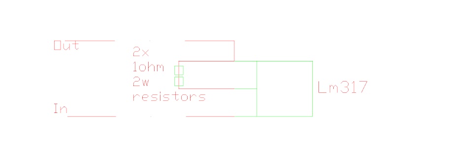
Well, i built this LM317 today but when i test it with my own test load i fail, the current is allways 0. I'm sure there is current trought arriving to the LM317 (tested with multimeter).
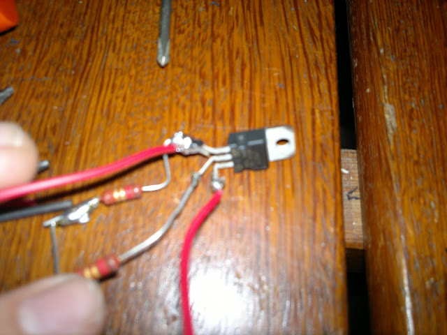
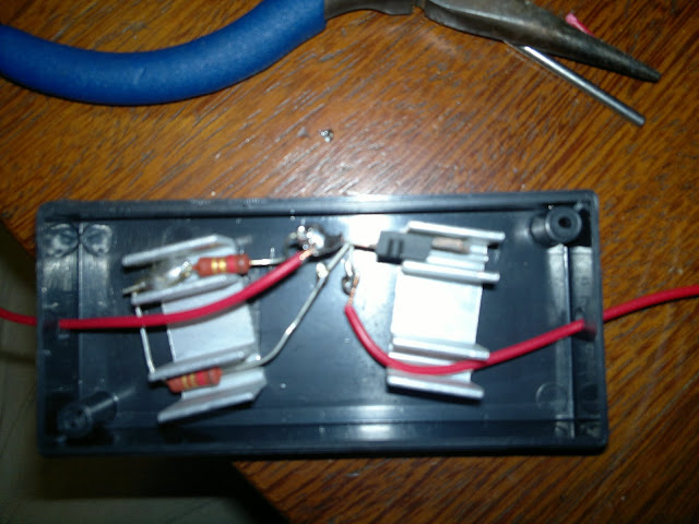
What may be wrong? Can you please check if i connected it right?
Is my LM317 broken? How can i check if it's broken?
Thanks...
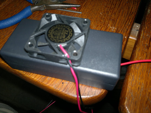
Photos:
What may be wrong? Can you please check if i connected it right?
Is my LM317 broken? How can i check if it's broken?
Thanks...
Photos: