LPF Donation via Stripe | LPF Donation - Other Methods
Links below open in new window
ArcticMyst Security by Avery


You are using an out of date browser. It may not display this or other websites correctly.
You should upgrade or use an alternative browser.
You should upgrade or use an alternative browser.
My First Laser Driver
- Thread starter Yankee
- Start date


- Joined
- Aug 30, 2008
- Messages
- 260
- Points
- 18
Studying the DDL driver is a great reference for driver construction. Also several users on this forum offer drivers for sale, in a kit form, or built. Rckstr has some good pdf files on building his drivers,
Cheers
Dave
Cheers
Dave
I'm still learning to navigate this site and so far I've come across only one built driver. It looks like a good regulated driver, but I don't know if it has the optical feedback.
Are any of the kits or built drivers offering regulation with the optical feedback? If so, where do I find them? Thanks in advance!
~ Dave
Are any of the kits or built drivers offering regulation with the optical feedback? If so, where do I find them? Thanks in advance!
~ Dave
So, it seems as though I've been reading some old information and please correct me or confirm. I just read the data sheet for the Sony SLD1239JL-54 diode and it says that the third pin is not connected. Have laser diodes evolved enough to not need optical feedback? Please remember that I'm an old dawg teaching myself new tricks.
~ Dave
~ Dave
rog8811
0
- Joined
- Jul 24, 2007
- Messages
- 2,749
- Points
- 0
I cannot think of any builds I have seen here that use optical feedback..... we just tend to use shared experience on the maximum current input, there are brave souls here who have blown any number of LD's on our behalf ")
A constant current drive, built and set up correctly, will do the trick for you.....good luck with your voyage of discovery, all the info you need is here.
Regards rog8811
A constant current drive, built and set up correctly, will do the trick for you.....good luck with your voyage of discovery, all the info you need is here.
Regards rog8811
Thanks Rog. I intend on not blowing "many" LDs, but I guess we'll see.
If there's one thing that I'm really good at, it's Power Circuits. I'm used to higher power, but it's all the same, just lower values. I'll keep y'all apprised of any findings.
~ Dave
If there's one thing that I'm really good at, it's Power Circuits. I'm used to higher power, but it's all the same, just lower values. I'll keep y'all apprised of any findings.
~ Dave
Kage
0
- Joined
- Mar 5, 2008
- Messages
- 285
- Points
- 18
Hey Yankee,
Glad to see another capable circuit board/power supply builder out there. I had the same problem trying to locate any schematics I really liked the looks of, and ended up designing my own, even though it ended up costing a bit for all the surface mount components and stuff. And again, like you, I thought at first that optical feedback would be the way to go, but there is actually a very good reason why it is not. Since we tend to overdrive the LASER diodes in our projects, if the laser started to degrade at all due to heat or an optical flaw or whatever, the circuit would try to pour more current into the diode and quickly KILL it! So it is much better to use constant current, especially for Bluray lasers.
If you are serious about building your own PCBs and have tools to handle surface mount components, I have schematics for several high efficiency circuits that can be built on .5"x.7" or so .1" spaced plated through perf-board. I also have parts lists with part numbers for a couple of them for purchasing the components from Digikey and or Mouser. I tend to use the LM2731"X" or LM3410"X" for most of these because the package they come in is fairly friendly. Also used a LTC3538 once but the package is very difficult to hand solder without a PCB layout. I do not sell anything or make kits or any of that so far, but I could post schematics if there is really any interest in them.
Another thing you may consider is the "Lavadrive" or "Flexdrive" from a member called drlava. I understand these work quite well and would be much cheaper than ordering parts to build one or two yourself.
Good luck with your projects.
Hey, thanks for the reply. I'm probably going to use one of the kits that you recommended for the first build. Once I get to know the LDs a little better, I'll lay out some proto boards.
I wouldn't mind seeing some of those schematics. I get most of the prototype parts for free through my suppliers. In fact, today, one of my suppliers gave me a $37.00 pre-built eval board for the National LM3404 LED driver. These things happen when you're in a position that allows you to spend a lot of money on electronics for Uncle Sam. When they find out that I'm playing with lasers, they'll be sampling me with drivers and maybe even LDs.
Also, I noticed a lot of people here trying to solder surface mount components using soldering irons. Tough job sometimes! There are much easier ways, like using an electric hot plate and an old iron skillet that will never be used for food again. Warm up the pan with the boards on it, using solder paste and watch the solder melt. For hobbyists, the solder temperature profile isn't all that critical, so long as you remove the board from the heat after 3 to 4 seconds of all of the solder melting.
Anther problem is placing solder paste onto the pads. If you don't want to spend $200.00 on a solder screen print kit, buy your solder paste in the tubes (I think they're 40ml); pick up a 16 ga. cattle hypo needle and grind the sharp point off; they fit right onto the end of the solder tubes. Then, make a plunger out of a piece of wooden dowel to dispense the solder. Next time I proto a board, I'll try to remember to take some photos to post here.
~ Dave
Kage
0
- Joined
- Mar 5, 2008
- Messages
- 285
- Points
- 18
Must be nice to get free samples! I work at a small company now, so free stuff isn't too likely for my home projects theses days.
Thanks for the tips on soldering small SMT boards. I bet you could do this on a kitchen stove, even. For those of us who don't have real steady hands any more (like me) this sounds like a good idea for sure.
I have done most of my prototyping of these drivers using double-sticky film and cardboard, using tiny hookup wire and a fine soldering tip - and a good mag light.
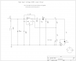
This schematic I will attempt to post, is for a driver I made to boost and better regulate the DX200 Red "dilda" laser that is sold on Dealextreme.com, but is apparently no longer available to those of us who live in the US except through third party purchases thanks to the FDA. It has a very capable Red LD, but a poor and inefficient driver.
Thanks for the tips on soldering small SMT boards. I bet you could do this on a kitchen stove, even. For those of us who don't have real steady hands any more (like me) this sounds like a good idea for sure.
I have done most of my prototyping of these drivers using double-sticky film and cardboard, using tiny hookup wire and a fine soldering tip - and a good mag light.
This schematic I will attempt to post, is for a driver I made to boost and better regulate the DX200 Red "dilda" laser that is sold on Dealextreme.com, but is apparently no longer available to those of us who live in the US except through third party purchases thanks to the FDA. It has a very capable Red LD, but a poor and inefficient driver.
Attachments
- Joined
- Feb 23, 2008
- Messages
- 2,832
- Points
- 48
chopper
0
- Joined
- Sep 21, 2008
- Messages
- 119
- Points
- 18
You can also check out Sam's Laser FAQ for a bunch of different driver ideas (and all sorts off other cool stuff laser related).
Here is a link to the Diode Laser Power Supply section.
http://www.repairfaq.org/sam/laserdps.htm#dpstoc
Here is a link to the Diode Laser Power Supply section.
http://www.repairfaq.org/sam/laserdps.htm#dpstoc
Kage
0
- Joined
- Mar 5, 2008
- Messages
- 285
- Points
- 18
Yankee said:ndrew thanks, but I think I'll leave the optical option alone per LPF user recommendations.
Kage, do you have desired output requirements available for that schematic?
~ Dave
Interestingly enough, I was just playing with the DX200 "Dilda" laser last night that I built the driver for. There is another thread here where one has been driven to 322mW! So, I tried it with mine. The pot maxed out at 275mW output (after the lens). I am pretty sure I tested the circuit to over 450mA with a dummy load originally, but dummy loads never quite have the same characteristics as the real thing. To get more power, all that should be needed is lowering the value of R3 a little. I will try it tonight. Also, I am not sure what current it is using to get 275mW - but I can find out simply by monitoring the 1 ohm ballast resistor (R4). I will post more info after a couple tests. I don't intend to try getting more than 300mW out because I'm chicken!
Kage
0
- Joined
- Mar 5, 2008
- Messages
- 285
- Points
- 18
I couldn't get to this until this afternoon, but the results are a bit interesting. Started by changing R3 to 3K.
Here are the readings I took:
Output mW* Current mA LD Volts Power Supply
239 409 2.95
275 485 3.12 375mA@6.7V
303 559! 3.30
*after the lens
Power was being supplied by a bench supply set to 6.7V to simulate 2 CR2 rechargeable batteries.
I would never have thought the LD would survive 500mA! I turned it On/Off several times at around 550mA and still it survives, but I am setting it back to 275mW before buttoning it back up. Pardon me if I don't test it to death, but not sure how hard these are to get now, plus it is epoxied in, sort of to hold the board in place.
Part of the design goal was to be able to operate from a single Li-ion battery, as a 14500 cell will fit in the Dilda in place of the 2 CR2s. But efficiency does suffer. When I dropped the supply voltage to 4.2V, the current In went up to over 700mA with the output set to 275mW, but it stays in regulation perfectly.
In the photo, the red numbers are Amps, DMM on the right is LD voltage.
Attachments
Kage
0
- Joined
- Mar 5, 2008
- Messages
- 285
- Points
- 18
CHP said:Kage,
Is the current you measured the current going to the laser diode or the current that is being input to your switching regulator?
Are you using a glass or plastic lens?
The current in that small chart is going In to the LD, but be advised that it is measured across a 1 ohm 5% series resistor, so is only +- 5% accurate at best + the effect of temperature on the resistor ( I don't know the coefficient for the resistor). Still, it is close enough to be sure the current is over 1/2 an amp at 300mW, but, it would be nice if someone else could verify this.
The lens is the original AR coated for red - I think they are glass.
