

Hi Guys,
As promised, here's my guide to bumping up the power output of a DMX RGY laser show unit.
I carefully dismantled my 350mw Laserworld EL-35RGY unit and took a few photos along the way.
I also discovered an easy way to bump up the power output using nothing more than a jewellers
screwdriver.")
The system used TTL blanking for the red and green lasers and 10 dmx channels.
It also has 200 built in patterns + sound to light, so it can also work as a stand alone unit.
On removing the cover I was surprised to see that the unit contained 2 red lasers combined
using a splitter/combiner glass cube. Using 2 x 125w red laser modules to make approx 250mw of red.
I think this is due to reliability and price reasons. As a reliable 250mw is quite expensive using a single
diode. (without overdriving that is)
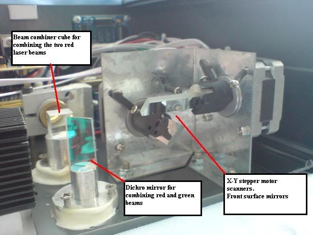
As you can see, the optical path contains quite a few components to combine 2 red and 1 green module.
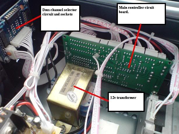
This is the main controller PCB and dmx interface.
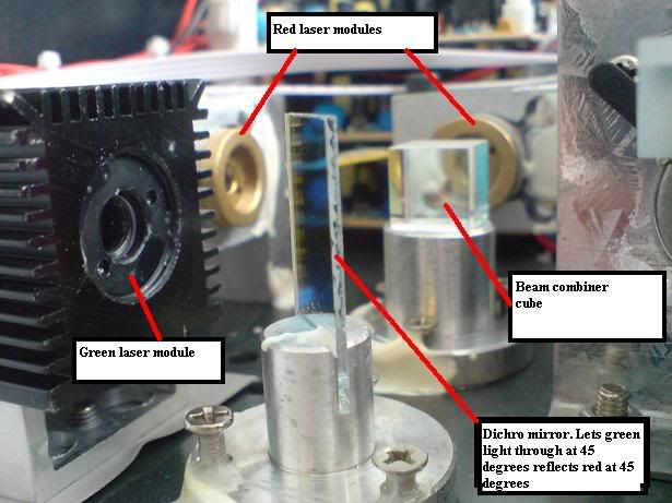
This is a closeup of the 3 laser modules and the main combiner cube and dichro mirror that
combines the red and green beams. The mirror reflects red at a 45 degree angle and the
green is allowed to pass through at a 45 degree angle.
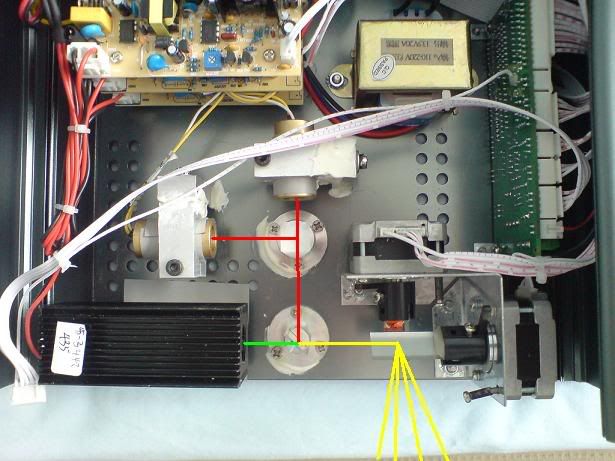
This is a top down view of the optical system and I've added the beam paths of each
colour of laser. Showing how the 3 beams are combined to make a yellow beam and
how they exit the x-y mirror scanning system.
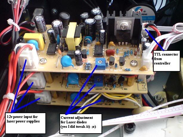
To bump up the power, I used a small jewellers screwdriver on the above power
supply boards. The top board is for the green laser and the middle and bottom ones
are for the two red lasers. I gave each one an clockwise turn. (on a clock it would be
from 12 to just over 1.
I've had over one hour of runtime and all 3 lasers still run cool and no mode hopping
with the green. But they are all noticeably brighter, especially the red which used to be
noticeably dimmer than the green. also when using red and green mixed in a 12 beam
fan formation, the yellow was uch more noticeable. Before it was more green than yellow.
I hope this helps answer a few questions on how to split and combine lasers of
different wavelengths.
If you have any questions or want more pics/info. Please feel free to ask me.
Heidi :-*
As promised, here's my guide to bumping up the power output of a DMX RGY laser show unit.
I carefully dismantled my 350mw Laserworld EL-35RGY unit and took a few photos along the way.
I also discovered an easy way to bump up the power output using nothing more than a jewellers
screwdriver.
The system used TTL blanking for the red and green lasers and 10 dmx channels.
It also has 200 built in patterns + sound to light, so it can also work as a stand alone unit.
On removing the cover I was surprised to see that the unit contained 2 red lasers combined
using a splitter/combiner glass cube. Using 2 x 125w red laser modules to make approx 250mw of red.
I think this is due to reliability and price reasons. As a reliable 250mw is quite expensive using a single
diode. (without overdriving that is
)
As you can see, the optical path contains quite a few components to combine 2 red and 1 green module.
This is the main controller PCB and dmx interface.
This is a closeup of the 3 laser modules and the main combiner cube and dichro mirror that
combines the red and green beams. The mirror reflects red at a 45 degree angle and the
green is allowed to pass through at a 45 degree angle.
This is a top down view of the optical system and I've added the beam paths of each
colour of laser. Showing how the 3 beams are combined to make a yellow beam and
how they exit the x-y mirror scanning system.
To bump up the power, I used a small jewellers screwdriver on the above power
supply boards. The top board is for the green laser and the middle and bottom ones
are for the two red lasers. I gave each one an clockwise turn. (on a clock it would be
from 12 to just over 1.
I've had over one hour of runtime and all 3 lasers still run cool and no mode hopping
with the green. But they are all noticeably brighter, especially the red which used to be
noticeably dimmer than the green. also when using red and green mixed in a 12 beam
fan formation, the yellow was uch more noticeable. Before it was more green than yellow.
I hope this helps answer a few questions on how to split and combine lasers of
different wavelengths.
If you have any questions or want more pics/info. Please feel free to ask me.
Heidi :-*


