Welcome to Laser Pointer Forums - discuss green laser pointers, blue laser pointers, and all types of lasers

LPF Donation via Stripe | LPF Donation - Other Methods

Links below open in new window

ArcticMyst Security by Avery

Looking to automate generation of power curve graphs with data logging capture device

DTR

0
Joined
Jun 24, 2010
Messages
5,684
Points
113
I had been keeping my eye out for some time for one of the guys making Meters for the Ophir heads to add an input plugs for the power supply and output to the laser diode so it could add current and voltage to the data logging output.

In lieu of that I have been looking around at a lot of stuff to be able to make something myself that will automate nice power graphs without having to manually input all the observations into excel from my power tests. I would need datalogging for two voltages and a current reading or I guess I could go with three voltages and use a measurement across a 1ohm resistor in mV for the current to the diode.

Been looking for a cheap datalogger that would work for this and looking for some suggestions. Mabye something like this would work for the three voltage logging method.
DI-145 USB Data Acquisition Starter Kit

Basically I want to capture in say 0.1 or 0.25 second increments the voltage from the power supply to the laser, the current from the power supply to the laser and the voltage from the output of the LPM to the LCD voltage meter display to give me three nice columns of V/mA/mW.


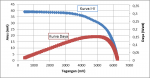
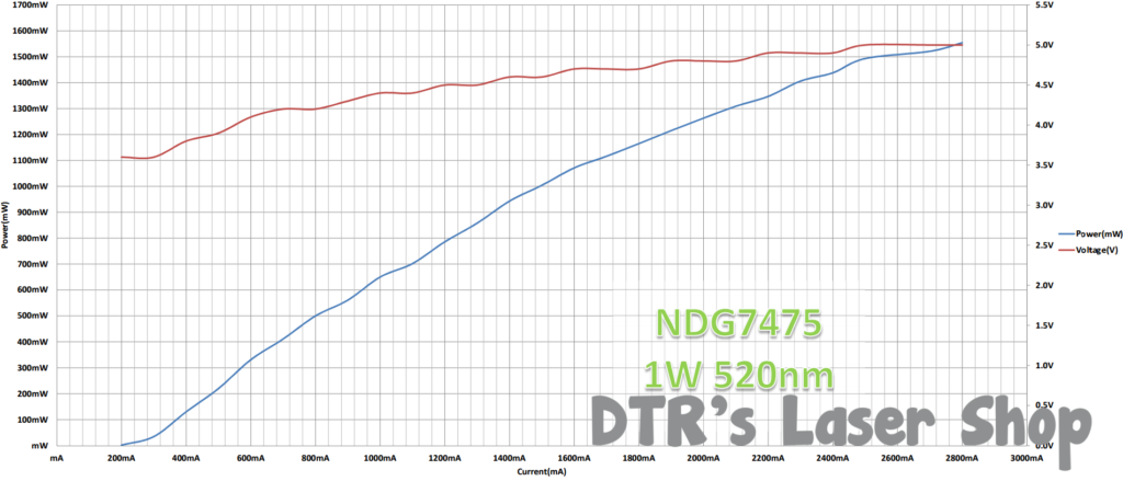
Anyway I can make ones like these the old fashioned way but would like for more resolution to give a better curve and less manual input and picturing. The waviness on this is due to the supply having a resolution of 100mA and not knowing if I am at 1-99mA in that range. I there is a fine adjustment on the supply which I can get my reading right when it flips to the next 100mA range but it is not seeming to be as accurate as I would like and it takes time while powered which makes heat more of a factor. Anyway seeing if there are any suggestions on a good setup.
7tbr6K.png


94Z28

2
Joined
Jul 1, 2016
Messages
539
Points
43
I think Astralist hyperion board is capable of this somehow with the kpm built in..

It's got the mA secton in his logging software so maybe it's a feature that is in development, but he said his chipset is efficiently a data logging platform for other purpose as well. Maybe he will chime in.. I was looking into doing the same thing but I was gonna tackle it after I get my new power supply (5A) kind of like what you have.

Let me know if you find anything out? If I get some info from Astralist I'll give you a shout.. his software is free if you wanna check it.
 
Last edited:

DTR

0
Joined
Jun 24, 2010
Messages
5,684
Points
113
Yea seen his thread saw it being used with a TEC based sensor in the picture which is too slow response but does look like he says it will configure or an Ophir or another faster response sensor. If it can work with faster response sensors and have the power source for the laser flow through it to capture that data as well that would be great.
 
Joined
Mar 27, 2011
Messages
504
Points
43
The DI-145 USB Data Acquisition Starter Kit only used a 10-bit resolution and i think that might be less accurate for your application. The price was good tho.

While being slightly OOT, this actually makes me remember about my thesis. Creating a data logger to read the IV curve from the solar cell, and then create a nice plot in excel (see attachement).

Meanwhile, i'm currently developing Hyperion Aurum which is an integrated board that can read from TEC, Ophir (powered within the board itself), and also reads current and voltage simultaneously.
It uses 24-bit ADC which means you'll get 0.298 uV and 2.98 uA resolution of voltage and current respectively (using current sensor which outputs 100mV per Amp).
But unfortunately i don't know when it'll be finished, as for now there is a bunch of other project needs to be finished :banghead:
 

Attachments

  • IVC.png
    IVC.png
    68.2 KB · Views: 140
Last edited:

Benm

0
Joined
Aug 16, 2007
Messages
7,896
Points
113
You seem to be quite busy designing things down there!

It would be really cool if it actually came with a constant current driver such that you could do the entire measurement with it. Ramp the current from zero to a set maximum and capture/log the results, but also take random data points to eliminate the effect of the laser heating up along the ramp.

If you read both voltage, current and laser power at the same time you'd have efficiency graphs as well, something often lacking now (many are current vs output power, neglecting that forward voltage depends on current too).
 
Joined
Mar 27, 2011
Messages
504
Points
43
That would be a good idea.
I can think of several IC (8A buck driver) to do the constant current driver, and the current itself can be controlled using digital potentiometer.
The drawback is that the current output will have an arbitrary step.

I can easily program the efficiency graphs once the hardware is finished :D
 

Benm

0
Joined
Aug 16, 2007
Messages
7,896
Points
113
Sounds like a nice idea then - a device you can simply connect a laser diode to and measure it's most important parameters automatically. This would also be very useful for efficiently binning diodes harvested from projectors and such.
 

DTR

0
Joined
Jun 24, 2010
Messages
5,684
Points
113
Yep that sounds awesome if a meter with all that incorporated was made. I would certainly pick one up. In the meantime I would still like to find a datalogger with the ability to log three voltage sources or better the current/voltage from one source and voltage from another. If three voltages the current would be read via the difference across a resistor so would probably need an accuracy of 0.01-0.05mV at the low and maybe 10V max also with readings every 0.1-0.25 seconds. Sounds like the one I linked to would work but not with the resolution that would be useful.

See stuff like this and wonder if used with three at one time it would work.
https://www.amazon.com/dp/B00YTWWQ7U/ref=twister_B0153836UE?_encoding=UTF8&psc=1
 
Last edited:

Benm

0
Joined
Aug 16, 2007
Messages
7,896
Points
113
I don't think this will be a complete off the shelf system.

To get it working well you'd need good sensors for current and voltage, which are not really problematic as things like shunts and adc's are readily available.

Another essential component would be a good laser power meter with digital output, and Astralists build seems a good option for this, as it is atmel based afaik.

One thing is getting the ADC part of things right. If you are thinking about an arduino based systems the on-chip adc's arent that accurate. You'd need to shift levels using opamps and such, or use external adc's to get good measurements.
 

AngelG

0
Joined
Nov 6, 2016
Messages
92
Points
0
It can be done. It could kill diodes in less than a second, leaving you w their I/V graphs and short memories :).
To control the current, there is a cheap ARM M3 Borad w 12-bit ADC (4096 points incl. 0) & 16 bit DAC;
I can program it to set the current via the LASER Diode to certain value by command from the PC. To do this, I need to create a PCB with LASER driver which accepts voltage 0..3.3V (from the DAC) and amplifies this to 0 .. 9.9V. The schematic is ready.
Next, I can create PC software to control the whole mess requesting current and writing the result Voltage.
The stability of the current & measurements will depend from the onboard 3.3Vstab. voltage source. It has max 1% offset.
I don't have hook-up guide for these "Ophir" power meters you use and their USB or RS232 protocol description. They look pretty expensive for my budget. So in my next reply I'll outline an idea about the poor guy's LASER powermeter.
What do you think ?
 
Last edited:

AngelG

0
Joined
Nov 6, 2016
Messages
92
Points
0
The poor Guy's LASER powermeter outline

Probably I should move this to the power meters topic.
The LASER powermeters usually use the principle of conversion of light power to temperature. So what it should consist of is:
- precision thermal sensors;
- optional heating + cooling elements (Peltier);
- thermo-conductive matte surface.
How would it work:
At given (fixed) thermal resistance, the difference between the temperature of the matte surface and the cooling element is proportional to the LASER power, which is being converted to heat. The heating is not a fast process: it would introduce delay, which we must deal with.
We need to measure the difference and calculate the LASER power.
For verification/calibration we could use an expensive power meter.

Details:
There is a good IR thermometer IC - MLX90614. It has I2C digital output.
The mate surface can be a piece of very thin anodized aluminum foil with fixed thermal-to- the cooling module resistance.
The sensor IC will measure the temperature of the foil. If there is no incoming power, the temperature of the foil will be equal to the cooling module (can be maintained at 20 deg Celsius). When somebody points a laser, the absorbed energy will cause heating of the foil, proportional to the power, e.t. temperature difference between the foil and the cooling module..
The response speed should be several seconds per point. It depends on the foil thermal capacity....
 
Last edited:


Top