Welcome to Laser Pointer Forums - discuss green laser pointers, blue laser pointers, and all types of lasers

LPF Donation via Stripe | LPF Donation - Other Methods

Links below open in new window

ArcticMyst Security by Avery

LM317 Question...no, a different one!

Joined
Sep 28, 2009
Messages
32
Points
0
Lesson learned, don't try to hook up multiple 5mw diodes with their own drivers off of a single power supply. I saw a puff of smoke from the board and burned out a nice little green number the other day :cryyy:.

So, I am trying to build a constant regulated voltage of 3.2 volts out using an LM317t. I am powering an array of 5mw diodes that already have their own drivers and they just need constant voltage. The reason for using the voltage regulators, is that I want to power all the diodes with one 18V bus supply. Therefore, I need to put each one on an isolated, regulated supply. The output from the LM317 will go to the standard setup of a 1N4001 and a 47uf capacitor. I don't want to mess with pots since I am doing fixed voltage and should be able to accomplish what I want with just resistors adjusting the output voltage. Can someone tell me how I can figure out what ohm and wattage resistors to use to accomplish this? What's the formula?


Joined
Oct 24, 2009
Messages
2,738
Points
63
"Ohm's Law defines the relationships between (P) power, (E) voltage, (I) current, and (R) resistance. One ohm is the resistance value through which one volt will maintain a current of one ampere."

To calculate the circuit voltage...
The formula is V = I x R
 
Joined
Sep 20, 2008
Messages
17,622
Points
113
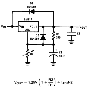
Here is a copy of part of the LM317 data sheet..
It is an Application schematic of a Variable Voltage
regulator... all you need to do is adjust it to your
required voltage... check the pot position resistance
and change it for a fixed resistor.... no calculations...

Start with a 5K pot... and you could get rid of the Diodes
for your needs..

317.gif


Jerry
 

Benm

0
Joined
Aug 16, 2007
Messages
7,896
Points
113
You can just calculate the values required using the formula, the IadjR2 part can be ignored for kilo-ohm range resistors. You would end up with 2k7 for R1 and 1k for R2 or resistors with a similar ratio (3.2/1.25=2.56).
 
Joined
Sep 28, 2009
Messages
32
Points
0
So I tried this circuit last night (sans diodes as suggested) and came up with somewhere right around 3.5 output volts, as measured by my volt meter. I put this on the 405nm and 650nm modules I have (both sealed with their own drivers), and both were extremely dim. These modules are supposed to run on 3.0 and 3.2 volts respectively. Any ideas what the problem is? I'm guessing that the driver circuits within them are sucking from the 3.5 volts I'm supplying, not leaving enough left to properly power the diode. My thought is that I'm going to have to play around with different output voltage values to match the driver circuits in each module. That's gonna suck, since they are sealed modules and I have no idea as to the individual components inside them.
 

HIMNL9

0
Joined
May 26, 2009
Messages
5,318
Points
0
The 3,5 volt you say, is referred to open circuit regulator, right ?

Have you tried also to measure the output with the modules atached and running ?
 

Benm

0
Joined
Aug 16, 2007
Messages
7,896
Points
113
Did you measure the voltage with the modules connected to this lm317 circuit?

The only problem i can imagine is insufficient input current or voltage for the lm317 to operate properly. You will need 3 volts more than the output voltage, so run in from a 6.2 volt or higher supply that can provide the current your modules draw to be safe.
 
Joined
Sep 28, 2009
Messages
32
Points
0
Did you measure the voltage with the modules connected to this lm317 circuit?

The only problem i can imagine is insufficient input current or voltage for the lm317 to operate properly. You will need 3 volts more than the output voltage, so run in from a 6.2 volt or higher supply that can provide the current your modules draw to be safe.

Ok, so I have a 6 volt supply at the moment...4xAA. I'm going to try a single 9 volt, and if still no go two 9s hooked in parallell.
 
Joined
Sep 20, 2008
Messages
17,622
Points
113
And for testing purposes... use only one (1) of your Lasers...
then the other... then both..

I would also check the output voltage of the LM317 circuit
while it is under load..
If it is lower than unloaded then you don't have enough input
voltage or your batteries are sagging (weak)..

Jerry


Top