Welcome to Laser Pointer Forums - discuss green laser pointers, blue laser pointers, and all types of lasers

LPF Donation via Stripe | LPF Donation - Other Methods

Links below open in new window

ArcticMyst Security by Avery

Laser with throttle capabilities

Joined
Jul 6, 2016
Messages
6
Points
0
I am interested in building a diode based laser with power throttling capabilities. I am interested in building one with a maximum power of 500mw or 1000mw maximum power, but I would also like to use the same laser at lower power. One practical benefit of throttling a laser is that I can adjust focusing and alignment with the laser at lower/safer power. I can also test for unexpected reflections at low power. I would like the laser to have 2 or 3 different buttons, so that I can change between power levels in an instant. Has anyone here heard of a laser driver with this sort of capabilities?

I am also thinking that I could design and build the driver myself, if there are no throttling drivers on the market. I do not need the device to fit in a small space, a larger device is acceptable. I do have electronics experience similar to an associates degree. It's been many years, so I may have to brush up, but I know there are ways to combine power transistors and operational amplifiers to act as current and voltage regulators.

If I design the driver myself, I see two different ways to throttle the power. I could simply have a current regulator with multiple settings. The disadvantage to this method is, I must get above the threshold current. Operating at a few percent of maximum power is difficult/impossible for some laser diodes. Another method of throttling a laser I would imagine, is to rapidaly pulse it. I could design the driver to create a series of 500ns laser pulses and alter the time between pulses to create a short duty cycle of 3% or less.

What do you think?


Joined
Jun 3, 2007
Messages
2,560
Points
113
Optotronics laser offer that as an optional feature for their lasers.
"Optional adjustable tail cap attenuator allows diode current tuning to 9 levels for maximum performance or ability to operate at lower power output levels."
 
  • Like
Reactions: GSS
Joined
Jul 20, 2011
Messages
723
Points
28
I have an M140 laser that uses a 5 mode led driver that allows 3 outputs as well as stove and sos, there are also 3 mode ones that just have low middle and high. There is a link to it in my sit.
 
Joined
Dec 12, 2012
Messages
854
Points
63
I second what bdgreenb said :D.

I've built one Mit's 500mW 638nm build using a normal 2-5 mode flashlight driver that used the common AMC 7135 chips. The disadvantage for this is that the lower power modes are pulsed, so although they are lower power, they aren't really that much safer.

The X-Drives can give lower power if only one Li-ion battery is used instead of the normal two, however that would require removing the batteries and probably isn't what you're looking for.
 
Last edited:

Benm

0
Joined
Aug 16, 2007
Messages
7,896
Points
113
Safety would depend a bit on how fast the switching actually is - if it's several kilohertz it may not be that big of an issue.

One downside of lowering laser power this way is that you get a funky dot-dash pattern if you sweep the laser beam across a wall and such.
 
Joined
Dec 12, 2012
Messages
854
Points
63
Safety would depend a bit on how fast the switching actually is - if it's several kilohertz it may not be that big of an issue.

One downside of lowering laser power this way is that you get a funky dot-dash pattern if you sweep the laser beam across a wall and such.

Last time I did a calculation I found it to be around 5 kHz.
So maybe not super dangers, idk, I haven't done any calculations. At 5 kHz, or whatever it is exactly, the pulses aren't really ever noticeable unless you are actually looking for them, or at least I don't notice it.
 
Last edited:
Joined
Sep 12, 2007
Messages
9,399
Points
113
Optotronics laser offer that as an optional feature for their lasers.
"Optional adjustable tail cap attenuator allows diode current tuning to 9 levels for maximum performance or ability to operate at lower power output levels."

You're talking about the "RPL", yes? I have one, and they're not even current regulated. The system relies on the small resistances in the tail-cap to limit the current. It's not a good design.

I have an M140 laser that uses a 5 mode led driver that allows 3 outputs...

The filtering on LED drivers tends to be rather poor. This is to save on cost, because LEDs don't really care. I'd recommending checking a driver out on an oscilloscope before using it for laser diodes.
 
  • Like
Reactions: GSS
Joined
Jul 6, 2016
Messages
6
Points
0
Safety would depend a bit on how fast the switching actually is - if it's several kilohertz it may not be that big of an issue.

Yes, I was thinking if I were to design the laser flasher myself, I would work in the kilohertz. For my first approximation I speculated 0.5 microseconds on and 16.5 microseconds off for about a 3% duty cycle. So a 500mw peak power would produce a 15mw average. This makes about 60 kilohertz. I arbitrarily chose 500ns for a pulse width, because it's way slow compared to how fast IC switches work and it's slow enough to not have to worry too much about RF signal bouncing and leaking (sort of guessing here).


One downside of lowering laser power this way is that you get a funky dot-dash pattern if you sweep the laser beam across a wall and such.

Not too worried about the appearance of a beam sweep


I've built one Mit's 500mW 638nm build using a normal 2-5 mode flashlight driver that used the common AMC 7135 chips. The disadvantage for this is that the lower power modes are pulsed, so although they are lower power, they aren't really that much safer.

Are there specs of what the flash rate for those drivers are?


Last time I did a calculation I found it to be around 5 kHz. So maybe not super dangers, idk, I haven't done any calculations.

I also choose something as short as 500ns pulse width, because I thought that it would not allow time enough to burn something. As far as dangerous I would avoid looking into such things as mirror reflections of the beam, even at of an on-500ns 3% duty cycle. But some times you get unexpected surface reflections that hit other surfaces. I would hope that a close call with one of those one of those indirect reflections would be less dangerous than a 100%-on beam..
 
Joined
Dec 12, 2012
Messages
854
Points
63
You can see my build HERE. Although the driver will only work with lower voltage diodes like the 638nm ones AFAIK. The pulse frequency was just what I calculated by indirect observation (look at my build thread), an oscilloscope would give much better data.
 
Last edited:
Joined
Mar 11, 2013
Messages
1,541
Points
83
You're talking about the "RPL", yes? I have one, and they're not even current regulated. The system relies on the small resistances in the tail-cap to limit the current. It's not a good design.

lame. I have one too. wondered how it was accomplished, suspected it was not current regulation. for such an expensive laser you'd think they would use a better way
 

Benm

0
Joined
Aug 16, 2007
Messages
7,896
Points
113
You can see my build HERE. Although the driver will only work with lower voltage diodes like the 638nm ones AFAIK. The pulse frequency was just what I calculated by indirect observation (look at my build thread), an oscilloscope would give much better data.

What exactly is the point of putting a finned heatsink on a driver, and then covering it in electrical tape so it will have zero airflow?

It would make more sense to just glue it to the case with some thermally conductive epoxy such that at least has -some- heatsinking?

The AMC chip will turn down ouput current when it overheats afaik, but this cannot work well for longer run times as the piece of copper is just a heat resevoir and it will not take that long for thermal protection to kick in.
 
Joined
Dec 12, 2012
Messages
854
Points
63
What exactly is the point of putting a finned heatsink on a driver, and then covering it in electrical tape so it will have zero airflow?

It would make more sense to just glue it to the case with some thermally conductive epoxy such that at least has -some- heatsinking?

The AMC chip will turn down ouput current when it overheats afaik, but this cannot work well for longer run times as the piece of copper is just a heat resevoir and it will not take that long for thermal protection to kick in.

The reason that I put an insulated heatsink (an oxymoron, I know) in was to do exactly what you said, use it as a larger "heat" reservoir for the chips. The only reason that I didn't use a solid copper block or other metal block was because that was the only one I had that would fit. Whether or not it actually noticeably improves the run-time I don't know, but I just figured I wanted to try something.
Adding thermal epoxy would also have been quite an improvement like you say, but I firstly didn't have any (and didn't want to wait!) and I wanted to be extra sure I never had to bother with a short anywhere inside there.

The AMC chips didn't dissipate very much heat at all in my build, so I don't know if heatsinking the chips are really that necessary.

I've actually been thinking about getting some thermally conductive epoxy recently, but I don't know which ones are better or not that good. And I just haven't gotten around to it:D.
 
Last edited:

Benm

0
Joined
Aug 16, 2007
Messages
7,896
Points
113
Oh okay. The fins will not take that much away by the looks of things, they make the thermal resevoir smaller by the amount of copper removed, but it looks like it's no more than 25% or so.

For the epoxy it's important to get something that is actually a 2 component system that hardens since you need to fill the space between a round wall and square heatsink. Something like arctic silver will work just fine.

Avoid single container glues and pastes, you want something that settles into a solid block for this. You should probably sand and clean the inside of the host tube before application as well to get a good mechanical bond.
 
Joined
Jul 6, 2016
Messages
6
Points
0
I will probably use the LED flashlight pulse based driver that Mattronium talked about. Because, I can get it up and running much quicker than designing my own driver. I'm not sure if I will ever invest the time to build something of my own design into reality.

However for some time, I have had an idea for a driver that has been rattling around my head that I would like to share with you. I do have AS EE education, but I don't get to apply it often, that said it is somewhat likely that I have overlooked important issues with my design.

Basically my idea for an adjustable pulse driver would be a sort of two-level current-driver. The driver would have a quiescent current mode and an active mode. Both modes would be adjusted once (unless you change laser diodes). The quiescent mode will drive the LD at a trickle current less than the threshold current. In active mode the drive would drive the LD with enough current to laze. I chose a non-zero current even when the LD is "off" because the voltage across the LD does not go to zero even when the current sharply decreases ( dE/dI with constant Temp) .

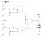
Using analog opamp computing as a guide, I came up with a preliminary design with 3 opamps and 2 Zeners. One Zener is driven by a resister connected to Vcc. The other Zener is driven by the output of a pulse generator connected to a resister. The constant voltage from each Zener goes into an opamp-voltage-divider circuit. Each voltage-divider is built with a potentiometer so they are independently adjustable. The output from both halves is blended similar to an opamp analog add-er. That is to say, both signals go through a there own resister before being merged. The merged signal is then used as the reference voltage to an opamp-power-transistor based constant current driver. The circuit feed from Vcc controls the quiescent current and the circuit feed from the pulse generator controls the Active current. See attached schematic

Please forgive the hand drawn nature of the schematic. Also note that is a a preliminary design that I have left vague. If the circuit is built in reality I will probability use resister potentiometer combination instead of just a potentiometer. Also I will probably use some sort of a buffer on the signal input. A buffer who's output is either tied to ground or Vcc depending on wheter the input is high or low. Also note, if I ever build it, I will probably design the power suply and signal generator to be tethered to the host, instead of inside the host.
 

Attachments

  • Laser-driver-2.png
    Laser-driver-2.png
    81.6 KB · Views: 96
Joined
Jun 3, 2007
Messages
2,560
Points
113
You're talking about the "RPL", yes? I have one, and they're not even current regulated. The system relies on the small resistances in the tail-cap to limit the current. It's not a good design.


The filtering on LED drivers tends to be rather poor. This is to save on cost, because LEDs don't really care. I'd recommending checking a driver out on an oscilloscope before using it for laser diodes.

I did not know. I'm sure others like knowing that too.
 

Benm

0
Joined
Aug 16, 2007
Messages
7,896
Points
113
Using analog opamp computing as a guide, I came up with a preliminary design with 3 opamps and 2 Zeners. One Zener is driven by a resister connected to Vcc. The other Zener is driven by the output of a pulse generator connected to a resister. The constant voltage from each Zener goes into an opamp-voltage-divider circuit. Each voltage-divider is built with a potentiometer so they are independently adjustable. The output from both halves is blended similar to an opamp analog add-er. That is to say, both signals go through a there own resister before being merged. The merged signal is then used as the reference voltage to an opamp-power-transistor based constant current driver. The circuit feed from Vcc controls the quiescent current and the circuit feed from the pulse generator controls the Active current. See attached schematic

What you drew up there looks pretty good. I'd add a small resistor between the last opamp and transistor base to improve feedback characteristics of that part (direct connection gives a very high current rise for a small voltage rise near 0.7v or so, requiring more gain/bandwidth to compensate for overshoot).

As for the zeners: You can use 1.25 references there, or just simple silicon diodes biased forward to get 0.6-0.7 volts maximum or so. This works well if you want to keep a low voltage across your sense resistor, but the opamp has to rail-to-rail common mode. Do not try to build this with 741's or something like that, it does not work.


Top