Welcome to Laser Pointer Forums - discuss green laser pointers, blue laser pointers, and all types of lasers

Buy Site Supporter Role (remove some ads) | LPF Donations

Links below open in new window

FrozenGate by Avery

Laser Brighter after screwing up aixiz module

icey17

0
Joined
Apr 6, 2010
Messages
3
Points
0
Hey

I recently bought a Rkcstr driver, PHR 803T sled and aixiz housing and put everything together today.

From first connecting the battery the diode worked and a very small hard to see violet dot appeared, but the dot couldn't be seen from 2 metres away in the dark, so I attempted changing the pot, which did nothing to increase the brightness.

After I decided to try putting the module in the housing, but after completely screwing up the aixiz module the laser grew MUCH brighter. Does anyone have any idea why this could be?

Thanks in advance :)


Something probably accidentally rubbed the pot and turned it up. I'd be wary that it could decrease the laser's lifespan.
 
You may have had a poor connection on one of your solder welds. Screwing the module together could have squeezed the connection tighter. If the poor connection was on the negative path, the rear opening of the module could have even cut into the wire enough to give you the good connection.

If it is working well, I would just leave everything as is and enjoy it. Unscrewing it could cause the poor connection to fail completely

Peace,
dave
 
Thanks for your help guys

I figured out it was a poor connection with one of the wires.

Sadly when I went to screw the back of the aixiz module on a second time the pins broke off the diode (:() so I will have to buy a new blu ray diode.

In the next diode, if I leave the driver outside of the module, is that ok (I don't see any reason why it should be different, my red has a driver outside) anyway, just asking, thanks :)

Get a hot glue gun too, so you can really hold that driver at the back of the diode. Sometimes screwing in that Aixiz driver holder twists things.
 
You can put the driver outside the aixiz module. Soldering driver boards directly to the diode can be tricky. If you do, make sure the board is not jammed flush to the diode or front part of the module when soldering the connections.

The problem is that te leads expand from the heat when soldering, but contract back when it all cools down. This might seem like a minute effect, but if you press the board to the module during soldering, it can be enough to break a solder weld (or a pin) when things cool down. So leave some slack in the wires, and make the mechanical connection with glue/tack/silicone/etc.
 
Thanks for your help guys

I figured out it was a poor connection with one of the wires.

Sadly when I went to screw the back of the aixiz module on a second time the pins broke off the diode (:() so I will have to buy a new blu ray diode.

In the next diode, if I leave the driver outside of the module, is that ok (I don't see any reason why it should be different, my red has a driver outside) anyway, just asking, thanks :)

As posted above, you can simply leave the rear of the aixiz off. However, if you want/need it, I have found that the Rkcstr fits beter if I sand the sides and rear of the driver down just a bit. You can sand it down almost to the components without ill effects. You do have to make sure that no metal from the driver is touching the module, but it is easier with it a bit smaller.

Aslo, opening up the rear of the aixiz a bit with a drill helps.

Peace,
dave
 
I'd really recommend against sanding down any component or board, unless you know exactly what you are doing. Getting the driver to fit within an aixiz module is nice, but its not a good step when starting out with lasers - give things the space they require until you are very comfortable with the technology!
 
Okay, an update on my situation...

I finally received my new blu-ray diode, and have soldered everything together, but the light still looks extremely dull. After putting the new diode in the housing, I left the back casing off the module and soldered it to the driver. Using a 4.5V current, I started with the pot turned right down, and tested the draw on the battery, which was the same as the pot turned down with my fully functioning red, but even after turning the pot halfway up, the brightness didn't increase. (shining the laser against white paper in the dark)

The brightness of the diode is the same as before I screwed in the aixiz module on the old diode, (which then lit up very bright (and didn't die)).

Anyway, I have included these pictures, so hopefully you can get a better idea of what's happening.

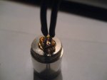
Aixiz module with diode inside, I am wondering if those boards on the back are the problem?
IMG_3042.JPG
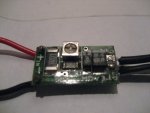
Front of the driver
IMG_3039.JPG
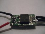
Back of the driver:
IMG_3037.JPG

Thanks guys for all your help :)
 
Well first of all, LIVE current setting is a REALLY bad idea.

This is what you do - get ONE OHM resistor, and connect it insteaed of the diode in the driver.
Next, grab you voltmeter and set it to mV range (200mV is good), and measure the milivolts across the 1ohm resistor.
Adjust the pot so that you read 100mV on your resistor.
Ohms law says that Current equals Voltage divided by Resistance:
I = U / R (U, or V, voltage in European and American standards, respectively)

So if your resistance is 1, dividing by 1 returns the same number so
U = I in your case ,
Hence
100mV = 100mA through your diode.

Now, be aware that this will work only with LM1117 and similar linear regulators, for boost drivers such as Lava's Flex and MicroBoost drives, you need proper dummy load which simulates laser diode (consists of 6x 1n400X diodes AND 1ohm resistor in series).

Adjust your current to 100mA first, then connect diode.

Live current setting may/ and often results in a voltage/current spike which will kill your diode quickly. turn off the unit discharge the cap and then adj the driver this is the way to do it.
 
Okay, an update on my situation...

I finally received my new blu-ray diode, and have soldered everything together, but the light still looks extremely dull. After putting the new diode in the housing, I left the back casing off the module and soldered it to the driver. Using a 4.5V current, I started with the pot turned right down, and tested the draw on the battery, which was the same as the pot turned down with my fully functioning red, but even after turning the pot halfway up, the brightness didn't increase. (shining the laser against white paper in the dark)

The brightness of the diode is the same as before I screwed in the aixiz module on the old diode, (which then lit up very bright (and didn't die)).

Anyway, I have included these pictures, so hopefully you can get a better idea of what's happening.

Aixiz module with diode inside, I am wondering if those boards on the back are the problem?
View attachment 27439
Front of the driver
View attachment 27438
Back of the driver:
View attachment 27437

Thanks guys for all your help :)

If you are still working on this. 4.5V with a bluray and Rkcstr is NOT enough voltage. You need at least 7.2V at the power source (batteries) to run this combination. The diode needs ~5V. The driver needs 2.2V

De-solder the diode, hook the driver up to a test load and set the driver current where you want it. Use at least 7.2V

Bottom line = You need more voltage

Peace,
dave
 
Yes, the little printed circuit boards on the back of the diode could be problematic. Most people remove them.

Also, you're probably going to want to press your diode much deeper, or else you're likely going to have problems focusing. I use a little piece of 1/8" stainless tubing and a vise for this. You actually want to have the back of your diode pressed in below the surface of your module. Just deeper than flush, or all the way in, if you prefer. You'll be able to focus easier (this is near-essential with 405nM diodes,) and you'll optimize the heat transfer from diode to module.

Lastly, those really are nice pics. Very clear. Props to decent photography!


Back
Top