Welcome to Laser Pointer Forums - discuss green laser pointers, blue laser pointers, and all types of lasers

LPF Donation via Stripe | LPF Donation - Other Methods

Links below open in new window

ArcticMyst Security by Avery

Laser beam profiler - CCD sernsor vs. 5mW beam

swissz

0
Joined
Apr 23, 2010
Messages
3
Points
0
Hi!
I would need for my research study a laser beam profiler, unfortunately these devices are very expensive and I just don't have the budget for one.
I think I could use the CCD or CMOS chip of a digital SLR camera for this purpose, but before I risk it, I would like to ask you about whether a CCD/CMOS detector could survive the direct irradiation of a three different 5mW lasers (red, green and violet, one at a time), if the diameter of the irradiation spot is ~2mm. Does anyone have some experience?
I browsed the forum and I found stories about damaged chips, but in these cases the laser were a bit more powerful 30mW-200mW.

Regards


Benm

0
Joined
Aug 16, 2007
Messages
7,896
Points
113
Its hard to tell. With the damaged camera's, you also have the lens that focusses the incoming beam into a pinprick on the sensor (at least when focus is set for infinity). Thats obviously a great increase in power density that would be bypassed if you shine a laser at the sensor directly.

Doesnt the sensor manufacturer specify some absolute maximum value for exposure?
 
Joined
Aug 20, 2008
Messages
709
Points
0
Most CMOS and CCD sensors are extremely sensitive; you will probably saturate the detector if you shine a laser at it... Have you considered using a high OD filter of some sort?
 

HIMNL9

0
Joined
May 26, 2009
Messages
5,318
Points
0
Get a set of ND filters for photography ..... the ND filters are sometimes found in batches, like this one, a package with an 1-stop, 2 stop and 3 stop (ND2, 4 and 8) that can be mounted one in front of the other, so you can make a "multiple value" filter ..... with the 3 you can combine them for get from 1 to 6 stops, so it's 1/2, 1/4, 1/8, 1/6, 1/32 and 1/64 of the light passing.

Mount the 3 together, place them in front of the CCD (you ofcourse have to take away all the lenses and use the bare CCD, for that what you want) and start to measure, if you see that the beam is too faint through 6/stop, decrease it to 5, or 4, til the image is clear enough for give you a good result without saturate the CCD ..... if they are not enough, adding another 3-stop (ND8) you can increase the range and number of combinations ..... anyway, always start with the more attenuation, and decrease it, never the opposite.
 

Benm

0
Joined
Aug 16, 2007
Messages
7,896
Points
113
Using ND filters seems like a good idea.

I would be careful with sticking multiple ones on top of eachother though: Those things dont come with the best of AR coatings, so you might see some internal reflections that mess with what you actually want to look at.
 

HIMNL9

0
Joined
May 26, 2009
Messages
5,318
Points
0
^ true about AR ..... there's a possibility, but require some work in mechanic, too, for avoid this.

Mounting the filters at 40/45 degrees in the beam path, using 10mm spacers between them, can take care about the internal reflections, but in this case, you need to build a CCD holder that not just repair it from the surrounding light and hold the mount for the filters, but also permit you to shift it in one axis, cause the filters can "shift away" the beam for their internal diffraction, so, each time you add or remove a filter from the stack, you need to displace the CCD until the beam is again in the center (or, more easily, displace the laser holder :p
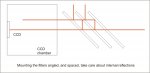
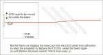
) ..... basically as in the pics.

But i agree, the better solution may be to find different values ND filters and use them one each time ..... but, if is relatively easy to find cheap 2,4 and 8 levels, going to 16, 32 or more is not so easy or cheap .....
 

Attachments

  • beamprofiler01.jpg
    beamprofiler01.jpg
    60.8 KB · Views: 486
  • beamprofiler02.jpg
    beamprofiler02.jpg
    98.5 KB · Views: 497
Joined
Aug 15, 2009
Messages
1,443
Points
48
A common way to view for example interference patterns or beam profiles is to use a CCD camera without any lens, just let the beam hit the sensor directly. This way you don't focus it and see nothing but a destroyed sensor but the beam profile becomes visible. Something special about beam profilers is that the CCD sensor doesn't have a protective cover glass. When you shien coherent light on it, this cover glass and the sensor form an etalon which can screw up what you see. So you may have to remove the cover glass of the CCD sensor to prevent fringes in the beam profile. The CCD chip is fragile though, the sensor will probably degrade and get damaged without the cover glass, it may even die when you try it.

To attenuate the beam you can use neutral density filters, I've always used pretty strong filters, OD4 to start with and between OD 1 and 2 extra. That's about a million times attenuation. The limit here is not to shoot your filters to pieces. So when I needed to get a beam profile of a high power pulsed YAG, we just took the transmission through a 45 deg HR mirror with a polished backside. The ND filters were still needed though.

Another way to pick a small part of the beam is to pick a reflection of an uncoated wedge. Because of the wedge shape there won't be a double reflection overlapping.

HIML9, it looks nice but it won't work nice. Any surface has reflections, even more at an angle. But at an angle this willl produces a displaced copy of the beam, a ghost beam. Even more with multiple filters. It's best to use only a few strong filters and the reflections will have the same beam profile anyway. Dust on the filters will be the most irritating anyway.
 

HIMNL9

0
Joined
May 26, 2009
Messages
5,318
Points
0
^ another idea ..... getting a sanded glass screen, focus the beam on it, and focus the CCD with its lens on the other side ? ..... not exactly in the path of the beam, just on the beam image formed on the sanded side of the screen .....

This way can be used filters and closed diaphragms without affect the image of the beam ..... (ok, not for high power pulsed units, maybe, but for "normal" lasers, it can work ..... have to find some of these glasses somewhere and try this myself, one of these days .....)
 
Joined
May 1, 2009
Messages
181
Points
28
I use standard CCD cams to catch the beam profile. To avoid damage of the CCD chip you can measure the beam indirectly (e.g. a black beam target) or put a piece of an old CD (without any label etc.) in front of your cam. Works fine even with a 1W IR beam.

To differenciate between different wavelengths (808nm - 1064nm) just use a simple line diffraction grating or prism. In ~1m distance you can easily see the maximas...

And all of this is cheap, cheap, cheap... :)
 

Ijat

0
Joined
May 10, 2010
Messages
1
Points
0
I use standard CCD cams to catch the beam profile. To avoid damage of the CCD chip you can measure the beam indirectly (e.g. a black beam target) or put a piece of an old CD (without any label etc.) in front of your cam. Works fine even with a 1W IR beam.

To differenciate between different wavelengths (808nm - 1064nm) just use a simple line diffraction grating or prism. In ~1m distance you can easily see the maximas...

And all of this is cheap, cheap, cheap... :)

Hi
Could u pls explain more on how to measure the beam indirectly...the black beam target...

tqvm
 

swissz

0
Joined
Apr 23, 2010
Messages
3
Points
0
Hi!
Thanks for your ideas and suggestions. Now, what I made is similar to HIMNL9's suggestion with the sanded glass screen. I just use a simple white sheet of paper, as it is close to a Lambertian scatterer, and I focus my camera on this sheet. Ok, it is a very cheap solution, but it can show some trend in my measurements. Unfortunately, the size of commercial CCDs is too small to be used directly with strongly diverged beams, but with this setup it's not a problem either.
 

HIMNL9

0
Joined
May 26, 2009
Messages
5,318
Points
0
Hi, i today got a very cheapy webcam (around 7$ equivalent), so i decided to mangl ..... er, i mean, "dismantle" it for see if it can be used as "beam profiler.

The webcam is this one:

attachment.php


And, as you can see, is extremely cheapy built, too ..... single SMD chip all-integrated functions, including the USB interface .....

attachment.php


Very small sensitive area, so is virtually impossible to use it shining directly the beam to the CMOS sensor .....

attachment.php


And also, the chip is so bad, that keeping the cam circuit without enclosure, and closing the front lens with lightproof cover, it still gives you this image (yes, it's the light that pass through the PCB and hit the back of the cmos chip, filtering through it ..... the rectangles are the shadows of the soldering pads under the chip :p) ..... and it goes only to 640x480.

attachment.php


But i found the only good thing, about it ..... the (cheap plastic) lens holding tube have a thread so long, that i can focus an object inside the lens holder cone, almost one or two millimeters from the lens surface ..... and a "light screen" cone in front of the lens, filled of steps (where i can rest and glue something flat, if the dimensions are good) ..... also, perhaps that the geometrical correction of the lens assembly, is good til few mm from the lens (almost no "fish-eye effect") ..... so, this gave me an idea ..... re-enclose the camera in its own case, then make a "screen" of "sanded" glass, or policarbonate, the one i can find / work more easily, and glue it inside the lens holder cone, then focus on its sanded surface, place an ND filter in front of the lens, and shine the beam on the screen (maybe keeping all inside a black tube, for not left the external light interfer)

I'm actually searching a decent way for obtain a small disc from a thin sanded glass piece that i have around (without tear it totally in chips :p), once i reach to do this, i will left you know the results ..... maybe this can become a cheap way for build a hobby level beam profiler, too :D
 

Attachments

  • cbp01.jpg
    cbp01.jpg
    269 KB · Views: 2,024
  • cbp02.jpg
    cbp02.jpg
    304.8 KB · Views: 2,143
  • cbp03.jpg
    cbp03.jpg
    294.3 KB · Views: 2,692
  • cbp04.jpg
    cbp04.jpg
    142.1 KB · Views: 2,136


Top