Welcome to Laser Pointer Forums - discuss green laser pointers, blue laser pointers, and all types of lasers

LPF Donation via Stripe | LPF Donation - Other Methods

Links below open in new window

ArcticMyst Security by Avery

issue with test load, dmm bad? Diodes bad?

Joined
Feb 21, 2011
Messages
143
Points
0
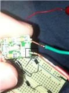
I was soldering and doing fairly well for my first time of soldering such a small thing, and the green pcb had tinned spots for "+" and "-" to be soldered on which would then be connected to the diode. I was just doing it to connect to my test load and it was going well till i had to "re-solder."

Upon re-soldering the situation worsened as certain tinned spots started to turn black. I'd rather "fail" on this driver than on the driver i plan on using, and on the diodes.

Are these black spots, that seem to occur when any solder touches the green PCB material in that same spot or around it currable?
 
Last edited:


Joined
Jul 17, 2010
Messages
2,160
Points
0
Re: Cheap driver PCB turns black?

How hot is your soldering iron? It also could be that the masking has been contaminated from the manufacturer. As long as the solder points and traces are intact you should be ok.
 
Joined
Feb 21, 2011
Messages
143
Points
0
Re: Cheap driver PCB turns black?

How hot is your soldering iron? It also could be that the masking has been contaminated from the manufacturer. As long as the solder points and traces are intact you should be ok.

The soldering tip itself (part of it)melted off...So i guess pretty dang hot: and i think all other solder points are intact the only place that that solder point connects to is....the trimpot (which is on the other side of the mount).

(only reason why i was resoldering is because i tried it out (the driver) and it didn't do what it was supposed to do, noticed the diode that runs to the trimpot was directly connected to the "output" of the trimpot and the input at the same time cause of my solder trailing slightly.)

But my main issue is the solder will not stick to that black spot no matter how hard i try...should i get some flux and paint over the black spot with it?
 
Joined
Jul 17, 2010
Messages
2,160
Points
0
Re: Cheap driver PCB turns black?

You've burned off the point were the solder was intended to go. If You can find the trace that runs to these places take an Xacto knife and carefully scrap a small spot through the masking, and then try soldering there. If however you cannot find the trace or any other connection the PCB is a lost cause.
 
Joined
Feb 21, 2011
Messages
143
Points
0
Re: Cheap driver PCB turns black?

You've burned off the point were the solder was intended to go. If You can find the trace that runs to these places take an Xacto knife and carefully scrap a small spot through the masking, and then try soldering there. If however you cannot find the trace or any other connection the PCB is a lost cause.

oh ok, thanks, i'll take a look at that and see if i can salvage this thing.
 
Joined
Feb 5, 2008
Messages
6,252
Points
83
Re: Cheap driver PCB turns black?

Black paint on PCBs arise when you "delaminate" the copper clad off it.

Copper layer is stuck with some sort of adhesive. It's normally clear, but when subjected to extremely high temperatures (more than what was meant to solder with), it'll melt away and turn black in the process.

Here's a video explaining it:
YouTube - How to destroy a PCB

Also, please take a look here:
SMD How To - 1 - SparkFun Electronics
That's first out of 8 pages which will make your day, explaining helpful tips and tricks of SMD soldering :)
 
Joined
Feb 21, 2011
Messages
143
Points
0
Re: Cheap driver PCB turns black?

Thank you Eudaimonium! (sorry for the late reply, my net was down for a few days).
 
Joined
Feb 21, 2011
Messages
143
Points
0
Re: Cheap driver PCB turns black?

I seem to have fixed it doing what is called "green wiring" to fix it (went directly from the trimpot to output, instead of from the "surface mount pad" that was there) and i get outputs that are somewhat desirable (assuming that the amount of voltage drop is correct for this driver 6 n(blah) diodes (the standard test load diodes) and a 1 ohm resistor) Gives a 0mV at the output resistor. I would like to turn the trimpot however, it is so small i do not know what size screwdriver to use: anyone know how these small surface mount trimpots can be turned? Like what size screwdriver or do i use tweasers?
 
Joined
Feb 5, 2008
Messages
6,252
Points
83
Re: Cheap driver PCB turns black?

Can we get a picture of what exactly did you solder, and what are you trying to achieve?

Also, picture of your entire setup when you are measuring output current? It would help greatly with troubleshooting :)
 
Joined
Nov 28, 2010
Messages
292
Points
18
Re: Cheap driver PCB turns black?

Questions
1.When soldering; do you use any flux/ if yes, what kind?
2.Every soldering iron should have a sticker or engraved power rating in watts / what is on your soldering iron 25W, 50W or ?
3.Screwdriver part - inexpensive solution= go to Dollar Tree, and ask for SKU # 588178 (Tool Bench Precision Screwdriver Sets, 12-pc. Set)
 
Joined
Feb 21, 2011
Messages
143
Points
0
Re: Cheap driver PCB turns black?

Well, i did find out that it was a flat head screw driver and not a philips screwdriver. So, i got the trimpot working now. The trimpot does work (it changes the voltage difference from input and output) however whenever i take a measurement of the the voltage across the 1 ohm resistor it gives me a 0, but there is voltage going through all other diodes just not the resistor. + this resistor looks weird...it has a "1*ohm*J" on it instead of standard markings. pics soon. (btw this is a cheap driver 405nm 100-300mw Laser Diode Driver Reverse Protection | eBay) and i was planning on using this to power my red build sense i'm using jibs for my violet build.

Flux: yes, i got rosin core and a actual container of rosin for soldering. The one i had before had no wattage on it it was a cheap one i got from walmart. The new one doesn't get as hot, its a 15W soldering iron. I figured out the screwdriver issue: i was trying to use philips but it wanted flat head.

Driversolder.jpg

The black square is where its soldered to the trimpot (sorry don't have a very good camera) its directly connected to the dome of the solder that is on the trimpot.

TestLoad.jpg

In this picture (sorry for the messy board) is the power supply. The power supply is a wall plug set to 6V DC then going through a voltage divider to get it to 3v (two 240 ohm resistors). The power into the driver + and - are on the bottum, so is the power out of the driver +. Where the - is on the other side of the bread board.
Should i be using the wall supply through the voltage divider?
 
Last edited:
Joined
Jul 17, 2010
Messages
2,160
Points
0
Re: Cheap driver PCB turns black?

Is the + output of the driver going to the 1st diode, and the - to the resistor leg? Make sure your diodes are connected like this ( + >I > I> I>I >I >I Resistor - ) because if the polarity is wrong you won't read anything at the resistor.
 
Joined
Feb 21, 2011
Messages
143
Points
0
Re: Cheap driver PCB turns black?

yep they are all connected that way. But i know what the driver does...it sets the voltage at point - to be set while the voltage at point + is changing but point - is not a 0 volts or negative for that matter but is a + voltage. The difference from point + to - causes a current to flow through all the diodes and the 1 ohm resistor. However the 1 ohm resistor (this one at least) acts as if its a short wire :(. Anyone know which type of resistor you guys use? I think its an issue with the resistor.
 
Last edited:
Joined
Feb 5, 2008
Messages
6,252
Points
83
Re: Cheap driver PCB turns black?

You can try measuring current at the input of your driver directly , so instead of (Battery+ -> Driver+), do this (Battery+ -> DMM -> driver), with DMM set to mA reading mode, not mV as before.

Or if you're expecting large currents, go for 10A measurement mode. In that case, 350mA will read as 0.35 . Just don't forget to re-connect your probes to appropriate sockets.

That's the advice I can give based on description, the pictures are way too blurry and infocused to tell anything from them.
 
Joined
Feb 21, 2011
Messages
143
Points
0
Re: Cheap driver PCB turns black?

Yet again, sadly i don't have a good camera (yet) just got my iphones camera for now. But i'll give that a try and see if it fixes the issue: i do have a old DMM.
 
Joined
Feb 21, 2011
Messages
143
Points
0
Re: Cheap driver PCB turns black?

Update: i tried the connecting the power supply>>> DMM>>>driver>>>test circuit and it seems to not pull much current at all(roughly 1micro amp, if not less). Yet again, i think the voltage drop is too large on the diodes. It seems to go - voltage about half way through (at 3 diodes) 1st diod drop is to 6.4 from 7.3, then from the next its -1.23 from 6.4, if i have a resistor that has a 1ohm times J symbol (usually this means its inductive) does that mean its a inductor? cause i ordered a resistor, and if i connect my old craftsman digital+analog multimeter 82320 it seems to give it as a ~~~=1.0 ohms resistance. Why would jibs AND the other driver give me this same issue with a standard test circuit?

Resistor is not the issue: J=+/-5% of 1 ohm. still curious. nvm, got it working, had to swithc around some diodes one diode was not connected right, now it works :).
 
Last edited:


Top