rhd
0
- Joined
- Dec 7, 2010
- Messages
- 8,469
- Points
- 0
A long time ago Sinner built me a version of one of his hosts that takes 3S3P 18650s (ie, it takes 9x 18650s). It's a monster. I've decided to build it into a flashlight, rather than a laser, so I picked up a COB LED that requires 42V.
So - I needed a boost driver to boost 11.1V nominal voltage from the 18650s into 45V. Nothing existed that was small enough, so I set out to design my own.
The IC with the highest output current that was also capable of 42V output is the LT1370HV.
http://cds.linear.com/docs/en/datasheet/1370fs.pdf
It JUST makes the cut (its limit is 42V). It's a fairly straightforward IC.
Where things get a little challenging is in making a ZXCT1009 work at voltages above 20V. I have followed the application note here:
http://www.thierry-lequeu.fr/data/AN45-zetex.pdf
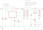
and am using a zener, transistor, and resistor, to increase the output voltage so that it will hopefully be able to handle sensing on a +42V line.
Would anyone mind taking a look at this schematic and telling me if I've missed anything? In particular, I'm not sure if my R1 value of 2.4k makes sense. They use 56k in the application note above, so I'm departing from that fairly significantly. The application note says to choose the value based on bias current of the zener, but the datasheet doesn't list the bias current. I just picked 10mA and calculated for R1 on that basis, but that's somewhat arbitrary.
Attachments
Last edited:


