Welcome to Laser Pointer Forums - discuss green laser pointers, blue laser pointers, and all types of lasers

LPF Donation via Stripe | LPF Donation - Other Methods

Links below open in new window

ArcticMyst Security by Avery

help with wiring

Joined
Dec 5, 2007
Messages
100
Points
18
hello i know that i am going to get all of my laser parts for xmas
What i have (or getting)
-16x sony DVD diode
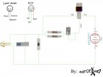
-laser diode driver kit (from stonetek .com)( 2"x2" PCB board, LM317, 2 10 Ohm Resistors, 1N4000 series Silicon Diode, 47uf 16v Capacitor, (2) sets of 6" lengths of two color wire, 24" Silver Solder, & 100 Ohm Pot
-aixiz mod.

thats it i am a little confused on wiring this baby i know that the bottom prong on the diode is the negitive and the right one is the positive
the only thing is that i am confused on is wiring the pot the the diode. i have looked at some schematics but i am new at those i just started using a bread board a while ago
so if some one could kindly post a detailed picture that would be great


D.


Joined
Sep 25, 2007
Messages
209
Points
0
I suggest that you don't use a breadboard with this. Laser diodes are picky about intermittent power, and this circuit will fry the diode if the connection is broken even for a split second. Instead, bite the bullet and fully solder this one together.

As far as the pot is concerned, you wire one leg to the output pin of the LM317 and the other leg to the adjust pin of the LM317. The laser diode will connect between the adjust pin of the LM317 and the ground line. Your capacitor will be connected directly in parallel with the laser, too. I'm sorry, I don't have a picture at the moment, but I hope this helps.
 
Joined
Nov 9, 2007
Messages
1,045
Points
0
Heres one that shows the actual components of it to make it easier..

(does anyone know how to put pictures without having to attach them?)

...lazer... ;D ;D ;D
 

Attachments

  • prototype_001_001.jpg
    prototype_001_001.jpg
    145.7 KB · Views: 7,805
Joined
Dec 5, 2007
Messages
100
Points
18
thanks a lot guys i saw that picture a little after posting the topic also i did a little snooping this morning and i found out that my parents bought two of the laser diode driver kit so i am just waiting untill xmas to do this

also i think i am going to have my friend help me with this because i am a little new at this and someone that is captain of out schools robotics club i think he should help me
also if any one else has something to say about that please please tell me i need all of the help i can get

also can i power this baby from a cell phone battery i use these to power a lot of LEDs to make a large flashlight a while ago it has 3.6 or somthing

i will keep looking at this picture untill i know it well


D.
 
Joined
Aug 15, 2007
Messages
790
Points
0
So long as you don't try to pull more current than the battery is rated for, and the voltage stays above 6V, the circuit will be fine.
 
Joined
Dec 5, 2007
Messages
100
Points
18
i am a little confused looking at the picture i know it is all preaty much stright through but how do you connect the blue dewhicky (its the first this next to the laser diode it just seems weird) but what do i know?
 
Joined
Nov 9, 2007
Messages
1,045
Points
0
Its a capacitor, you must have it to give the diode a long life, you just put it stright in paralel with the wires, the stripe on it tells which leg you should put on the negative side.

...lazer... ;D ;D ;D
 
Joined
Dec 5, 2007
Messages
100
Points
18
wooooooolazer said:
Its a capacitor, you must have it to give the diode a long life, you just put it stright in paralel with the wires, the stripe on it tells which leg you should put on the negative side.

...lazer... ;D ;D ;D

thanks i knew it was called a capacitor but iwanted to make sure and that you with the quick response
 
Joined
Aug 15, 2007
Messages
1,880
Points
0
GUYS - there's a serious problem here.

The resistors and pot should be between ADJ and LD, not Vout and LD. This has been discussed many times in Experiments and Mods. I know some schematics are wrong.
There should be nothing between Vout and LD +. Except connections to diode + cap + resistors.

THIS will most certainly drop your performance as the Vout must pass through resistors too. The only thing that matters with the adjusting resistors is that they are between adj and vout. Considering it's desirable that Vout go straight to LD, they should then go on the Adj side. see pic.
 

Attachments

  • schematic.gif
    schematic.gif
    3.5 KB · Views: 460

Gazoo

0
Joined
Jun 9, 2007
Messages
3,206
Points
38
Hate to tell you this Blu but your diagram is wrong. The resistors and pot do go between the Adj. and Vout. Then a wire is connected from the Adj. to the LD.

There is nothing wrong with the diagram wooooolaser posted.
 
Joined
Dec 5, 2007
Messages
100
Points
18
i am a little confused on the POT the wat the picture is taken it is hard to see the way it goes
 
Joined
Sep 25, 2007
Messages
209
Points
0
Blue, the reason the LD has to be connected off of the ADJ pin is because the chip needs to use it as part of the reference circuit.

Known facts about the circuit:
The laser diode will try to draw more current at a higher voltage.
The LM317 uses a 1.25v drop relative to Vout to determine whether it should increase or decrease its output.
By Ohm's law (E=I*R), the higher the current goes in the whole circuit, the more voltage the resistor drops before it can reach the ADJ pin. This means that with a resistance of 5 ohms between Vout and ADJ, a complete circuit will have the resistor drop 1.25V at 250mA.
Next, you need a complete circuit. This is where the LD comes in. Tie the LD between the ADJ pin and ground, and it will carry as much current as it can. In this case, the LM317 will ensure it only gets 250mA current, because it wants to maintain that 1.25v drop across the resistors.

If you place the laser diode in parallel (from vOUT to GND) as per your diagram, the chip can't monitor the power draw through the laser at all. It can only monitor and adjust what it sees across the resistors. In addition, there is no tie to ground anywhere, so the circuit is incomplete. The chip will sit at maximum output, trying to get a voltage reading it will never see. Therefore, the laser diode does not have any regulation on its input.
 
Joined
Aug 15, 2007
Messages
790
Points
0
BlueFusion said:
GUYS - there's a serious problem here.

The resistors and pot should be between ADJ and LD, not Vout and LD. This has been discussed many times in Experiments and Mods. I know some schematics are wrong.
There should be nothing between Vout and LD +. Except connections to diode + cap + resistors.

THIS will most certainly drop your performance as the Vout must pass through resistors too. The only thing that matters with the adjusting resistors is that they are between adj and vout. Considering it's desirable that Vout go straight to LD, they should then go on the Adj side. see pic.


The current must pass through the resistors. That is the entire point of the circuit. As the current flows through the resistors, the regulator is able to sense the voltage drop across the resistors (This is why it is called a sense resistor.) and adjust the voltage to the Vout pin to be equal to 1.25V + the forward voltage drop of the LD at the current set by 1.25V/Rsense. If the current to the LD is not going through the sense resistor then the regulator will try to get the voltage at Vout as high as possible in a useless attempt to get a 1.25V drop from the Vout to the Adj pins.

Please see my post here.
 
Joined
Dec 5, 2007
Messages
100
Points
18
hey i have another question i know that this circut you guys posted is to make the laser last a long time and i know that theres an easer way with out the LM317 capassaters and resisters. because i saw a video on youtube
does any have the circuit diograhm that goes from the diode to the pot and then the power sourse if so can you please post it


the reson why i am not looking for the hard way to do it is becuase this is my first time builting one and i have two of everything i need (i accidentally ordered two)

soo


D.
 
Joined
Nov 9, 2007
Messages
1,045
Points
0
you could put it in a minimag aa but you will be lucky if it lasts 2 days, youd even be lucky to get it to last 5min cause of the voltage spikes and amount of current it sends to it.

...lazer... ;D ;D ;D


Top