Welcome to Laser Pointer Forums - discuss green laser pointers, blue laser pointers, and all types of lasers

LPF Donation via Stripe | LPF Donation - Other Methods

Links below open in new window

ArcticMyst Security by Avery

Help with Blu ray laser and driver.

Joined
Dec 11, 2008
Messages
12
Points
0
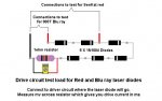
I'm in the process of building my first Blu ray laser. I have all the parts, but I am not sure how to build the driver.

The parts for the driver available:
LM317T
100 Ohm pot
2 1N4001 diode
1 15 Ohm resister
10uf 16v cap
47uf 10v cap
a little orange circle with a "104" written on it
PCB

I couldn't find a diagram of a DDL for a Blu-ray.

Thanks in advance.


Joined
Oct 27, 2008
Messages
726
Points
0
It is the same build as far as I know...just set the pot to the range you want...what's the orange circle for? :-?
 
Joined
Dec 11, 2008
Messages
12
Points
0
Um, I don't know. ;D
So, can I use a 15 ohm resistor for daedal's diagram and change nothing else and have it still work for a BR?

Thanks.
 
Joined
Oct 27, 2008
Messages
726
Points
0
Well After you build it hook it up to a DMM and see the power output adjust your pot to get in the proper output for your diode
 
Joined
Dec 11, 2008
Messages
12
Points
0
Once the driver is all assembled, can I just hook up the DMM right where the diode would be, or do I have to do anything special?
Sorry if I sound stupid as this is my first DIY.
 
Joined
Dec 11, 2008
Messages
12
Points
0
Ok, so I've built the driver and all I need to do is attach the diode to the driver. My diode has a ribbon and a tiny pcb attached to the pins. The Positive and Unused pins are soldered together and there is a tiny wire that goes around connecting all three pins. Do I have to take off the tiny pcb and wires or what?

Thanks
 
Joined
Jul 24, 2007
Messages
2,749
Points
0
Yes, you need to take it all off so that you can see the brass back of the LD can.
The way I do it to clamp the laser diode whilst it is still in the original mount. hold the ribbon cable in a pair of fine pliers, get some solder on the iron and put it between all of the pins on the LD, then carefully pull the ribbon cable and the PCB away.

Good luck ;)

Regards rog8811
 
Joined
Dec 11, 2008
Messages
12
Points
0
Ok, that was successful, but... is it fine that the positive pin is soldered to the unused pin?

And, how do you suggest soldering the diode to the driver with the minimum amount of heat.
 
Joined
Jul 24, 2007
Messages
2,749
Points
0
This is an 803T so all that will happen is that the case and module will be positive. so if you are mounting this in a flashlight you will need to put the batteries in the other way round.

I would assume you have already pushed the LD into a module, that will help disipate the heat, also make sure the LD pins aand the wires, to be connected are well tinned then you will not need to hold the iron the pins for too long.  It will help if you can clamp the module and the wires in the correct positions, this will leave you both hands for the soldering.

Regards rog8811

[edit] just thought if this is going in a flashlight the negative needs to go straight to the LD and the output of the driver will need to connect to the case...this is not easy to do....Far better to try and clear the solder bridge with either a solder sucker, solder braid or hold the module with the pins down heat the solder bridge then rap your hand (not the module!!!!) on the bench, the solder should fly off.[/edit]
 
Joined
Dec 11, 2008
Messages
12
Points
0
one last thing, for the pot on the driver, should I start having it tightened to the right or left? In other words, which way will block the most power.

Don't worry, I'm not using it in a flashlight.
 
Joined
Dec 11, 2008
Messages
12
Points
0
Thanks to all that helped! I just finished building and testing and... burned my first to matches!!
It just so happens that the components I used nicely made it so that it burned only at the max of the pot which should stop me from "accidentally" letting the screw slip to up the juice. =D

The only problem that I have now is that my super crappy module case doesn't have an adjustable focus and so its only a point at about 3 inches away. Now that I have pressed the diode into the module, is there anyway for me to easily pop the diode out and put it in an module that will be coming soon?

Also, I heard that Aixiz isn't the best acrylic module for Blu-Ray is that true and should I get a Sure module?

Thanks again
 
Joined
Jul 24, 2007
Messages
2,749
Points
0
Is it alright to use ten 10ohm resistors in parallel to equal one ohm

You can do that.....

But if you use 1 X 10ohm you can just multiply the mv reading by 10, so if you want 300ma output turn the pot until the meter reads .030v or 30mv (Depends how your meter displays).

It is far easier than using up all those 10ohms that could be used in drive circuits ;)

Regards rog8811


Top