Welcome to Laser Pointer Forums - discuss green laser pointers, blue laser pointers, and all types of lasers

LPF Donation via Stripe | LPF Donation - Other Methods

Links below open in new window

ArcticMyst Security by Avery

First Laser Build Questions

Joined
Jun 17, 2011
Messages
9
Points
0
Hi,

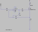
I'm interested in building my first laser and have a few question. First I'm an electrical engineer and have a decent working knowledge of circuits and general construction. My overall goal is to build a 1W 405nm laser, however I'm going to start small. I've designed a generic driver circuit that I believe will work with some minor modification up to 2A of continuous current. Attached is that schematic.
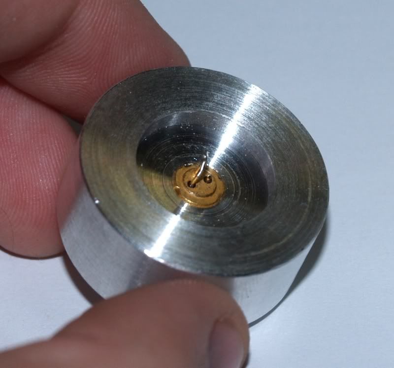
I have some questions regarding the housing of the diode however. The diode will fit inside a module, usually from aixiz. Is this the part that requires a press fit tool? Then the entire module fits inside a heatsink? Is there anywhere I can look to get examples of how the actually assembly of the diode should work and what I would need for this module, heatsink lens etc? Thank you very much for your assistance.
 

Attachments

  • driver.JPG
    driver.JPG
    20.6 KB · Views: 1,048


Joined
Feb 5, 2008
Messages
6,252
Points
83
Hey MHertzField,

First of all, welcome to this forum :)

Now, we all appreciate the DIY aspect of the hobby but there's no need to go around inventing new types of circuits when we already have everything we need to power everything we need.

Next, there's slight error in your plan. If you want around 1W of power or more, you do not want a 405nm diode, you want a 445nm diode. There's quite a difference.

Next, you'll read these diodes being pushed as high as 2.1 W of output, 2.3 Amps of current and what else... to be clear, that's just for novelty and sh*ts and giggles.

If you want your diode to live up to impress a fair amount of friends, and pay off being pricey build as it is, you do not want to go above 1.5 A of current.

Now, about pressfitting.
See, you do not need any kind of special tools or something. Just find a barrel that's flat on one end, and has a hole bored in it anywhere between 3 and 4 mm of width.

See, this is a diode perssfited in a heatsink:
P6140435.jpg


As you can see, all you have to do is apply enough force for 5.6mm diode to enter a 5.55- 5.58 mm wide hole (material is usually electroplated brass [Aixiz] or Aluminium [custom heatsinks]).

It's not a lot, but you do need a metal barrel described and a vice. If you don't have a vice, one of methods is to slowly hammer it in place, using a lot of weak but frequent hits on the back of the barrel.
This is generaly regarded as "last line of defense" though.

Also, let's be clear about what module is:
A "module" is a finished modular component of a system. Which in our case is accepted as a diode pressfited into a basic heatsink/housing with lens included, and with it's current regulation circuitry included in one way or another.

What you're referring to as "Aixiz module" is actually Aixiz diode housing.

So, what other questions do you might have I can help you with?
 
Last edited:
Joined
Jun 17, 2011
Messages
9
Points
0
Thanks for the welcome and the information. I personally don't feel the need to reinvent the wheel with the drive circuitry but I do have access to a generous supply of components at work. Only soldering required :).

Onto the housing, does the aixiz diode housing double as the heat sink or is an additional heatsink needed around the housing? Is there somewhere I can look to read about how to choose the right lens? Thanks again for all the help
 
Joined
Feb 5, 2008
Messages
6,252
Points
83
What I meant to say was, with that ciruitry thing, that for first build you can use your standard LM1117 or LM350 for needed currents no problems. No need to make your own.

And about the housing, well it's called a housing and not a heatsink.

See, all standard housings are 12mm in diameter, and basically just mechanically support the diode and the lens. So YES definetly a heatsink for that is needed.

On my picture up there, is a direct pressfit heatsink. So instead of securing 12mm module in 12mm hole, I make a 5.6mm diode pocket in the heatsink itself, so we just cut out the middle man and reap the benefits.
 
Joined
Jun 17, 2011
Messages
9
Points
0
Awesome, I think thats all the basic information I need to begin building. I want to start out a little smaller to get the basic idea down though. Can you recommend a good place to get some lower power diodes (probably 100~500mW) so that if I break something its not a $50 diode. Does anyone know where I can find some that arent in China? I'd prefer not to wait 4+ weeks for shipping. Thanks again!
 
Joined
Jun 17, 2011
Messages
9
Points
0
Awesome, I'll take a look. I thought of another question though, what are the safety requirements, for example glasses, that I should get. Is it safe so long as a dont look in the beam? I've read safety posts warning about people getting retina damage from reflections of laser, is that really something I should worry about?
 
Joined
Jun 17, 2011
Messages
9
Points
0
Another question, are you the one that makes the heatsinks and flashlight case kits in your link? If so i'll make sure to buy from you since you've been such a great help :)
 
Joined
Feb 5, 2008
Messages
6,252
Points
83
Ofcourse that laser reflections are a very real concern.

If you are getting a violet or red laser of no more than 200mW, it is not dangerous to look at dot projected on the dot a meter or two, or more, away.

Now, it is highly advisable to get yourself protections goggles, try Welcome to O-Like.com, Your source for laser products for that.

If you cannot afford them, just make sure to ALWAYS use common sense. Don't be stupid with your laser - don't point it in reflective and shiny stuff, and be mindful more of people around you, not just your own eyes.

And yes, I make heatsinks sold at Radiant Electronics - Home (they have the best violet and blue laser protection goggles around, also).
 
Joined
Jun 17, 2011
Messages
9
Points
0
Ok,

So I got my first diodes in and put them together. They worked fine for about 20 minutes in testing before they destroyed themselves. I had a rather simplistic setup for testing. I used a bench power supply, which was current limited to 500mA maximum, and a power resistor and current meter in series with the diode. I never went above the 500mA limit but they still destroyed themselves. Not completely either, they still output a small amount of light but nothing near where it should be. They were in the axiz case inside the lab style heatsink from modwerx. The only thing that I can think of as a failure condition was thermal runaway as I didn't use a thermal grease to ensure good contact between the axiz case and the heat sink. Any ideas on what I did wrong? Thanks again.
 

Morgan

0
Joined
Feb 5, 2009
Messages
2,174
Points
0
Welcome to world of murdering laser diodes! It happens to us all. You have turned your laser diodes into LEDs! Or, your laser diodes have LEDed, to use the vernacular...

I'm guessing from the current these were LPC-815 diodes? 660nm reds commonly called the LOC, (Long Open Can)? Do you have pics of them? What voltage was the bench PSU showing at death? With thermal run away I would expect to see it gradually climbing.

Personally, (so long as the PSU is stable and not all of them are. As I'm sure you know, they can be prone to spikes), I would just run the diode direct. No power resistor or anything. If you've checked the read out on the supply is fairly accurate, and depending on the resolution, you should be fine to trust it. At least for basic testing and learning purposes.

Assuming all else is correct, 20mins at 500mA is actually pushing them quite hard. I'd recommend you reduce to somewhere closer to 420mA max and even lower for testing and preservation, and use a sensible duty cycle. If the heatsink is getting to the, "Ooo, that's actually quite warm!", stage, then it's time to switch off and let it cool off! The official maximum rated specs for the LPC-815 diode is only 420mA, (if I remember correctly), pulsed at 50% duty cycle so we are already at twice that running it constant wave, (CW). Check out this useful link for compiled diode stats -

http://laserpointerforums.com/f51/d...-diodes-data-one-thread-45042.html#post601914

I hope that helps but you're well on the way...

M
:)
 
Last edited:
Joined
Apr 23, 2011
Messages
212
Points
0
Ok,

So I got my first diodes in and put them together. They worked fine for about 20 minutes in testing before they destroyed themselves. I had a rather simplistic setup for testing. I used a bench power supply, which was current limited to 500mA maximum, and a power resistor and current meter in series with the diode. I never went above the 500mA limit but they still destroyed themselves. Not completely either, they still output a small amount of light but nothing near where it should be. They were in the axiz case inside the lab style heatsink from modwerx. The only thing that I can think of as a failure condition was thermal runaway as I didn't use a thermal grease to ensure good contact between the axiz case and the heat sink. Any ideas on what I did wrong? Thanks again.

I like your circuit!!!! Very cool method for current limiting. ;)


Ouch, you fried blues? Those are expensive. If they were red diodes, you were pumping to much current into them. First of all, what was the heat? 20 minutes is a long time to be on, did you make sure that your heat sinking was adequate during that duration. How hot was it getting? I've never turned mine on longer than a few minutes because I don't feel my heat sinking is adequate.

Also, do you have a scope plot of the turn on characteristics of your driver? Current(/voltage) spikes are not good for your driver and can damage them over time.

One thing i'd try now, provided you have adequate heat sinking, is going up to 800mA and see if it start lazes again. Sometimes when you overload these guys they require more and more current to achieve a good output.
 
Last edited:

Morgan

0
Joined
Feb 5, 2009
Messages
2,174
Points
0
^ Do not try going to 800mA please.

@ random person - I think it was the intention of the OP to be buying cheap diodes to start with so they're unlikely to have been 445nm blues. It's also unlikely to have been a 445nm blue dying at 500mA. That is very low for them. 800mA is far to high though for what I suspect to be the LOC or similar. Until the diode is confirmed however we are both speculating so let's wait until we have the right information before continuing. 500mA is at the top end of a LOC but 800mA is way beyond it and may result in burning another diode for no reason.

Thanks,

M
:)
 
Last edited:
Joined
Apr 23, 2011
Messages
212
Points
0
^ Do not try going to 800mA please.

@ random person - I think it was the intention of the OP to be buying cheap diodes to start with so they're unlikely to have been 445nm blues. It's also unlikely to have been a 445nm blue dying at 500mA. That is very low for them. 800mA is far to high though for what I suspect to be the LOC or similar. Until the diode is confirmed however we are both speculating so let's wait until we have the right information before continuing. 500mA is at the top end of a LOC but 800mA is way beyond it and may result in burning another diode for no reason.

Thanks,

M
:)


^^^^ Listen to him before pumping more current. Sorry, was skimming the thread. Thought he was trying a 445nm blue. Mind posting a link to the laser diode you purchased MHerzfeld?
 
Last edited:
Joined
Jun 17, 2011
Messages
9
Points
0
Gentlemen,

Thank you for the responses, the actual diode was an LPC-826 as they were easier to get from modwerx than the 815. I could post pictures if you want, but it was the same open can style as the 815, just a slightly higher current. The modwerx description listed the max current as 600mA. (I didn't find the curves until later) Though I haven't seen anything about pulsing the diodes, I thought they were CW diodes, is this not true? If so where did you find that information. The voltage on failure was around 5VDC, the power supply is definitely accurate, I use it for testing my circuit cards at work :). With a forward diode drop of 2.5VDC and the power resistor set to 4 Ohms that would give me about 625mA which might explain the destruction, though I did have a current meter in series as the readouts on the power supply aren't horribly easy to read quickly. That never went above 500mA. I never noticed the heat sink getting warm, but its very possible that there wasn't good thermal conduction between the aixiz case and the heatsink, in which case there wouldn't be any heating. I'm planning on buying a few more reds just to get this down, so I can get scope plots of the current and voltage next time. Hope I answered all the questions, and here's the link.

LPC-826 laser diode 650-660nm 250-300mW [M0023] - $12.99 : Modwerx Shop
 

Morgan

0
Joined
Feb 5, 2009
Messages
2,174
Points
0
I think you answered the questions just fine. ;)

Hmmm, yes, the graphs do show runs up to 600mA but that is under test conditions to find the maximums. Some have continued to lase at up to 650mA but I'm not certain this will turn out to be a, 'super', diode. Initially look to be a touch better than the LPC-815 but there is not a huge amount of data on this diode at present, (I hadn't seen any figures myself until this thread prompted a search! I've been out of touch a little on latest developments due to work), so it's hard for anyone to be completely confident about a sensible safe current. My best advice to someone such as yourself just coming into the hobby...? Be conservative. At least until you can monitor your diode better, and gather more data, using an LPM, (your next essential tool btw).

As to the setup, I would ditch the power resistor and, (and DMM in fact), and just go with a real simple reading from the bench PSU as long as you have the resolution, (ie single mA measured, not in 50mA or 10mA divisions). As these diodes seem to be at little hardier when it comes to over current, they may survive the odd spike and from what you say yours seems pretty smooth anyway. Heatsinking is critical when pushing for the upper limits so spend a little time ensuring it is as good as you can make it. Arctic Silver and the like are not hard to come by, as you probably know, but can save a stressing diode.

If you haven't already then just punch in, "LPC-826", into the search box just above where the posts start. It'll bring up what we have already and the more that is posted, the clearer picture we get. (Further info is posted on other sites too remember... ;) )


The datasheet for the LPC-815 is in the, "Diode Compilation", thread I posted earlier but here it is again -

http://pagesperso-orange.fr/redlum.xohp/electronics/data/ML101U29.pdf

Many datasheets show figures for pulsed outputs because that's how the diode is intended to be used when in some sort of optical drive, (actually the datasheet above goes against that, but you can't have it all eh!). For example a diode may show figures for 300mW output pulsed, (often close to 50% duty cycle). In the application it is designed for it may last 10,000 hours. A very rough rule of thumb in the old days was to expect somewhere around the same output at CW but it'll only last maybe 100 hours. For a pointer, that's not bad. The rules changed with Blurays and the 445s and no doubt this LPC-826 won't follow that exactly either so it's down to those who have the cash and resources to do destructive testing of a reasonable number, from different sources to gain more fact based data. This you can help with when you have an LPM and a stable, reliable setup but for now, just enjoy the light! (And look after your peepers please) :)

I hope that's more helpful.

M
:)
 
Last edited:


Top