- Joined
- Feb 11, 2015
- Messages
- 16
- Points
- 0
I am preparing to build my first labby but was hoping some of the more experienced on this forum could check for any errors or red flags i might have missed :thinking:
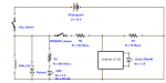
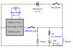
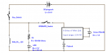
attached is the circuit diagram i have constructed, which lead to a few questions, but first i will give a detailed component list:
###########################################
Power Supply: regulated power adaptor (5V or 9V) max draw 2A
Key switch (safety): rated to 4A 28V DC
Operating switch: rated to 5A 250V AC
Fan: EITHER (5V 8CFM) OR (12V 19.3CFM)
LED: 2V at 20mA
Resistor: value depends on power supply. R=(Supply-2)/0.02
X-Drive v7 Mini: bought from flamingpyro, input range 2.5-9V, ouput 1A
Oclaro 700mW diode: bought from DTR, input: typ 900mA max 1.1A
Flyback Diode: EITHER (1N4004 400V @ 1A) OR (1N5404 400V @ 3A)
###########################################
And now, questions from a noob
1) I thought to put the flyback diode in to protect against any back current coming from the fan (i am unfamiliar with fan circuitry), but is it necessary?
2) I am having trouble choosing which power source to go for. the 5V would be safer for the driver but would mean a smaller, less powerful fan.
On the other hand, the 9V is right on the limit of the drivers input (not sure what the implications here would be) but would mean i could run a more powerful fan, a little under voltage unfortunately.
3) The wire i have is rated to 1.5A, is this cutting it a little too close or should i be okay?
4) There may, and quite likely is, other errors ive missed so please educate me and spare a poor diodes life :angel:
Thanks a lot guys
:thanks:
-------------------------EDIT--------------------------------
P.S That circuit was drawn using DoCircuits, an online tool. If any of you pros know of much better tools feel free to suggest
Attachments
Last edited: