Welcome to Laser Pointer Forums - discuss green laser pointers, blue laser pointers, and all types of lasers

Buy Site Supporter Role (remove some ads) | LPF Donations

Links below open in new window

FrozenGate by Avery

Driving a 500W LED Panel - High voltage, constant current, buck, capable of 7A?

rhd

0
Joined
Dec 7, 2010
Messages
8,469
Points
0
I may as well say this now, because you're going to be thinking it in a couple seconds. This is not a rational, practical, or particularly useful project.

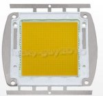
It's just really hard not to be intrigued by this:
500W Warm White 3500K High Power LED Light Lamp for Stage Street Bulb Illuminate | eBay
attachment.php


They require ~75V @ 7A, and I want to make that portable!

I envision using four (4) lipo packs in series, each of those packs in 6S configurations (22.2V nominal each). That would provide for 88.8V nominal, and reasonably easy recharging. 6S connectors are common, and a I've got a decent balance charger that can handle 6S. That would mean (basically) 4 separate packs to charge, which isn't a horrible burden (and this is far from a practical project anyway).

The challenge, is in designing (or even better yet, re-purposing an existing) driver. There are two hurdles here:

1) Voltage - Most of the common drivers, and driver ICs that we see, max out at around 30 or 35V. Buck circuits based on the LM2596 are all over eBay now, but they can't handle 70 to 80V of input.

2) Current - While 7A may be no big deal for a lipo pack to provide, it's a fairly substantial amount of current for a buck driver to handle.

It would be great to find something existing, that wouldn't require a custom PCB, reflowing, iterations etc. I'd go that route if it were the only option. The sad reality though, is that I don't have much free time for "fun" these days. Any thoughts - any ideas as to DC-DC drivers that might already be out there - would be much appreciated. I don't think I'd need to go current-reg with this, a voltage-reg should be fine, and reduce complexity.
 

Attachments

  • $(KGrHqNHJFIF!6SDOfrZBQgQ16,OOQ~~60_12.JPG
    $(KGrHqNHJFIF!6SDOfrZBQgQ16,OOQ~~60_12.JPG
    24.6 KB · Views: 3,969
Last edited:


Portable 500W led! You're crazy. What kind of host did you have in mind?

I don't know of anything premade that can handle that. If you want quick and dirty you might be able to throw together a simple unregulated buck with a 555 timer or something making pwm into this:
Buck Switching Converter Design Equations

Build it all through-hole on a protoboard so you don't have to wait for boards. You will need a big heatsinked mosfet for that though!

Also, at the bottom of that page is a link to calculator you can use to find component values. Looks like you need a 10uh 15A inductor and 100uf output capacitor with 84% switching duty cycle at 100khz.
 
Last edited:
I may as well say this now, because you're going to be thinking it in a couple seconds. This is not a rational, practical, or particularly useful project.

It's just really hard not to be intrigued by this:
500W Warm White 3500K High Power LED Light Lamp for Stage Street Bulb Illuminate | eBay
attachment.php


They require ~75V @ 7A, and I want to make that portable!

I envision using four (4) lipo packs in series, each of those packs in 6S configurations (22.2V nominal each). That would provide for 88.8V nominal, and reasonably easy recharging. 6S connectors are common, and a I've got a decent balance charger that can handle 6S. That would mean (basically) 4 separate packs to charge, which isn't a horrible burden (and this is far from a practical project anyway).

The challenge, is in designing (or even better yet, re-purposing an existing) driver. There are two hurdles here:

1) Voltage - Most of the common drivers, and driver ICs that we see, max out at around 30 or 35V. Buck circuits based on the LM2596 are all over eBay now, but they can't handle 70 to 80V of input.

2) Current - While 7A may be no big deal for a lipo pack to provide, it's a fairly substantial amount of current for a buck driver to handle.

It would be great to find something existing, that wouldn't require a custom PCB, reflowing, iterations etc. I'd go that route if it were the only option. The sad reality though, is that I don't have much free time for "fun" these days. Any thoughts - any ideas as to DC-DC drivers that might already be out there - would be much appreciated. I don't think I'd need to go current-reg with this, a voltage-reg should be fine, and reduce complexity.

Actually we run those here in Korea for street light replacements in around newer apartments. My recollection is that the ballasts are a fairly hefty size.....
there is a hack-a-day project for building a driver for 500W panels... below link.

Design of the LED Driver (v0.2)

Commercial driver below ->
RECOM Lighting - LED Drivers

Hope this helps...
 
RHD;

This is ambitious . . .

I can make it simpler, though.

Forget the driver.

Just add enough 4.2 VDC cells to obtain the max. current you need.

18 cells for ~67 VDC

The challange will be heat-sinking requirements.

Panasonic cells can handle ~6 amps.

Balance charge each group of 6 cells.

to maintain each cell maximum voltage at 4.2 VDC.

LarryDFW
 
Last edited:
I'm changing many of my lights here to LED.
Those AlGore pigtail bulbs are a joke as is he.
This 500W panel is amazing !!!
HMike
 
The challenge with not using any driver, is that with 18x cells, every 100mV drop causes almost 2V in total drop.

I've got to do a driver. My DNA won't let me ignore that step entirely. I couldn't find the hackaday 500W driver link. Mind posting it?
 
I posted all the links. They were in a very bad colour that blends into the background on the page. That is why you couldn't see it.
I just about missed the links too!!
This is supposed to be for a 500W LED such as the one you've managed to get a hold of.
I hope this proves to be of some use for you. It is in rev 0.2.

http://www.tbideas.com/blog/files/board-v0.2.zip

http://www.tbideas.com/blog/files/board-schema-v0.2.pdf

http://www.tbideas.com/blog/files/board-v0.2-BOM.csv

http://www.tbideas.com/blog/files/board-v0.2-sketchup.zip

Failing this, you could direct drive it..... A risky en-devour.
 
Last edited:
I'm pretty sure that design is for separate r g b leds, not one 500W one. May still work though.

Edit: Don't think that will work its 700ma per channel. Looks like a good candidate to make your own board with though.
 
Last edited:
I would consider using a linear driver for using this power led with those lipo's really.

The battery voltage is relatively close to the led operating voltage (percentage wise, anyway), so the losses would not be that big. The advantage of simplicity is a big benefit here. A switchmode driver that outputs 500 watts would be something very difficult to build. A linear driver that dissipates that 10 odd extra volts at 7 amps would not have to be anything spectacular. The part that actually does the work would be a few power transistors that can easily be mounted on a heatsink, perhaps with a fan if you want it somewhat portable.

The benefit of this approach is that you could make a negative side driver, and that the transistors would not even have to handle the full battery voltage, only the voltage difference between the batteries and the leds.
 
I'm pretty sure that design is for separate r g b leds, not one 500W one. May still work though.

Edit: Don't think that will work its 700ma per channel. Looks like a good candidate to make your own board with though.

however the description indicated that this driver could be used to drive a 500W LED on hack-a -day...

guess they were wrong....

:(
 
I posted all the links. They were in a very bad colour that blends into the background on the page. That is why you couldn't see it.
I just about missed the links too!!
This is supposed to be for a 500W LED such as the one you've managed to get a hold of.

I don't think it is actually. I couldn't find any reference to 500W, and the project details suggest using a 20V 2.5A input (50W). They also talk in some of the comments about adapting the board to drive 30W worth of LEDs instead of 10W.

As Ben suggested, it might be a candidate for further development. But I'd note that it's probably an order of ten-fold under the wattage requirements I'm looking for. At that degree of difference, it probably makes more sense to find another design that has a starting point a bit closer to my target.

I would consider using a linear driver for using this power led with those lipo's really.

The battery voltage is relatively close to the led operating voltage (percentage wise, anyway), so the losses would not be that big. The advantage of simplicity is a big benefit here. A switchmode driver that outputs 500 watts would be something very difficult to build. A linear driver that dissipates that 10 odd extra volts at 7 amps would not have to be anything spectacular. The part that actually does the work would be a few power transistors that can easily be mounted on a heatsink, perhaps with a fan if you want it somewhat portable.

Eeeek, that scares me. 7 amps x 10 volts of dropout = 70 Watts of heat to dissipate from a linear driver. And yes, I recognize the irony in complaining about 70W, given the context of what I'm trying to do here.
 
I just finished up a schematic, i'll transfer it to a board tomorrow and post it.
 
More or less what is used to drive the LED street lights here.
These are about 200,000W ea ~ $180CDN. I was in Yongsan Electronics mall yesterday and saw some 150W - 300W LED drivers for sale. The company looked like it had seen better days.... local economy here is pretty dead for small vendors.
 
Hope you've got a portable swimming pool to cool that thing, those LED arrays are ungodly inefficient when it comes to LED technology :p 70W in the driver will be the last of your worries.
 
Last edited:


Back
Top