Welcome to Laser Pointer Forums - discuss green laser pointers, blue laser pointers, and all types of lasers

LPF Donation via Stripe | LPF Donation - Other Methods

Links below open in new window

ArcticMyst Security by Avery

Driver connection help.

Peef

0
Joined
Jan 5, 2014
Messages
9
Points
0
Hi, first of all, sorry if this question has been posted already about this specific driver - I searched the forum but to no avail!

So I recently bought this driver from 'Laserlands' on Ebay, to use with a 2w 4445nm build - Adjustable Driver 450nm 445nm 473nm Blue Laser Diode 1W 1 4W 2W 3 5V 2 5A | eBay

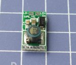
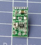
My problem is that I'm not confident of where to solder the battery leads and where to solder the diode leads. Here's the pics of front and back:

$(KGrHqV,!q8FG8khGoo+BRw9!Y,vH!~~60_57.JPG


$T2eC16ZHJGUFFhyL!ipbBRw8+t77!Q~~60_57.JPG


I see there's a LD+ and and :D- marked there, and assumed these are for the laser diode. I also saw the + on the opposite end of the board and assumed that was battery +. I asked the seller where to put the - input from the battery and he said that the - input is the outside of the 'di' (diode?), which just left me scratching my head. I asked again but got no more information - there seems to be a language barrier at work (he's from china).

I'm hoping there's someone here with a strong understanding of the working of a driver circuit, who can follow the circuit and see clearly what's what. I'd really appreciate if anyone can edit the pictures with arrows to what's what too! I've added the images as lower resolution attachments in case the links above don't work.

Any help at all is appreciated!

Steve.
 

Attachments

  • driver top cut.JPG
    driver top cut.JPG
    54.4 KB · Views: 147
  • Driver bottom cut.JPG
    Driver bottom cut.JPG
    51.1 KB · Views: 150


Tmack

0
Joined
Oct 13, 2013
Messages
2,478
Points
0
Well LD is laser diode. As for the battery ???? I see a positive plus by the bunch of holes, and at the other end of the driver I see the neg.
 
Last edited:

Peef

0
Joined
Jan 5, 2014
Messages
9
Points
0
Thanks for the reply, Tmack. Yeah, I see the same. The thing that concerns me is that what looks like the battery negative has a hole punched going through to the diode negative. Soldering at that hole at both sides is going to be risky as hell - bound to connect through it. With the seller saying battery negative is the case of the 'di' too, I suspect I'm missing something.
Maybe that the driver can be put in series with the battery and diode? I'm such a newb at this...
 
Last edited:
Joined
Sep 12, 2007
Messages
9,399
Points
113
The thing that concerns me is that what looks like the battery negative has a hole punched going through to the diode negative. Soldering at that hole at both sides is going to be risky as hell - bound to connect through it.

The hole is called a via, and it is designed to electrically connect two points. So I'd venture a guess that LD- and B- are electrically the same point anyway.
 
Joined
Mar 29, 2013
Messages
1,221
Points
63
AH! This is one of those of those drivers for case neutral diodes. So you could have the diode's case pin act as the negative pickup. Ah, i see.

:beer:
-Matt
 
Joined
Dec 29, 2009
Messages
3,136
Points
63
Yep, rather than get the battery - from a wire or from other metal in the host, it gets it from the unused pin on the laser diode, which on an isolated LD, is the pin that is electrically continuous with the case of the diode. You can verify this by making sure that the third pin on your diode (the one that isn't the + or -) does not have the ceramic or resin looking insulator around the base of the pin, but instead, that the pin looks like it's just directly connected to the back of the case.

This post and attached picture do a pretty good job of explaining why this works in a handheld build:
http://laserpointerforums.com/f55/r...-taking-payments-now-48664-21.html#post781362

It's just another way of achieving the end result: electricity has a path from battery (-) to the corresponding pad on the driver.
 

Peef

0
Joined
Jan 5, 2014
Messages
9
Points
0
Yep, rather than get the battery - from a wire or from other metal in the host, it gets it from the unused pin on the laser diode, which on an isolated LD, is the pin that is electrically continuous with the case of the diode. You can verify this by making sure that the third pin on your diode (the one that isn't the + or -) does not have the ceramic or resin looking insulator around the base of the pin, but instead, that the pin looks like it's just directly connected to the back of the case.

My brain, it hurts!

I can't get my head around how the diode case has anything to do with anything unless the diode's neutral pin, or the case, is connected to either Diode - or Diode +.

So if the LD - and battery - are at the same point on this driver, does that mean I can put it in series with the battery and diode? Battery + > B+ on driver, LD + on driver > Diode +, Diode - > Battery -.

Or maybe that same circuit with a 'T' junction from Battery - or Diode - to LD - on the driver.

*scratches head*
 
Last edited:
Joined
Jul 20, 2014
Messages
2
Points
0
Yesterday I burned one red laser by mistake when I disconnect the laser from a driver with the LM317 and connect it again, so the output was 5v....
Laser diodes are very sensitive for ESD or Electric Static Discharge, you have to read about it before you burn 30$ or 50$ diode :yh:
here is a good link if you are interested:
W's stable low noise LD driver

I have the same driver from ebay and a 1,4W blue laser.
I didn´t try it yet but yesterday I started to check the driver how it is connected and tried to draw a schematic, and here what I came up with(if someone can aprove it some values are missing like capacitors and the ic, I don´t know what is that):
laser%20driver-.jpg
 
Joined
Jul 20, 2014
Messages
2
Points
0
Please use the current test circuit to check that the current is not higher than the diode max rate!

https://www.dropbox.com/s/231bg562dybmf0e/laser%20driver-Current%20test%20circuit.JPG

https://www.dropbox.com/s/p564hh3dhd7juwl/laser%20driver-.jpg

I just tested now the connection and everything is working well!

Please connect an ampere-meter to check the current in the circuit, the ampere-meter must be connected in the power supply side not the LD side!

The minimum output current is when you turn the pot(VR) anti clockwise as shown in the images, it´s wise to turn it completely left(I don´t take any responsibility for that, depending on your circuit it can be the opposite! mine is as in the picture!)

Any damage for anything you did, you are the only responsible, this driver is not my product and I´m not professional in laser diodes or drivers!


Top