Welcome to Laser Pointer Forums - discuss green laser pointers, blue laser pointers, and all types of lasers

LPF Donation via Stripe | LPF Donation - Other Methods

Links below open in new window

ArcticMyst Security by Avery

DIY LPM Pics and Vid

Joined
Jan 14, 2011
Messages
3,816
Points
63
Hey all.

So for the last month or two I have been planning, thinking about, and building my DIY LPM from this circuit: http://laserpointerforums.com/f42/diy-thermal-lpm-under-50-a-51129.html.

I finally finished it yesterday. There are still a couple of kinks (depending on how the plug is situated, something shorts or something and causes it to measure directly the voltage that's incoming? I dunno. Anyway, it usually works.), but other than that, it works perfectly.

So here are some pictures of it.
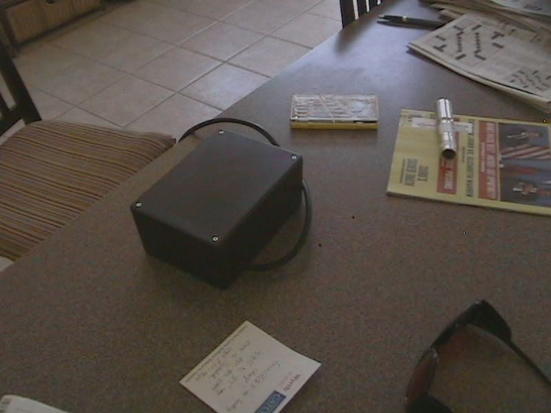
DCAM0061.jpg

The back.


DCAM0062.jpg

The TEC.


DCAM0060.jpg

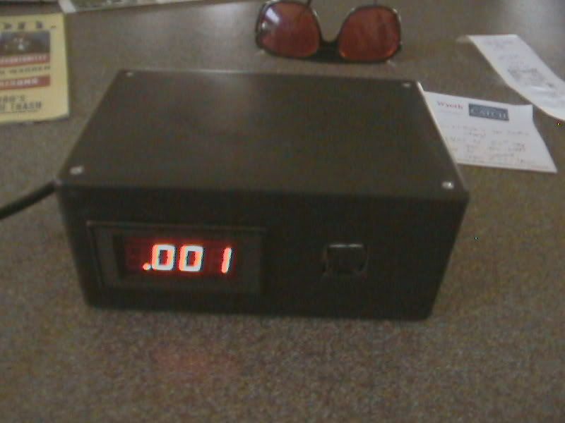
The front, in all its professional looking glory (or at least I think so).


And here's a video.
YouTube - ‪DIY Laser Power Meter‬‏

I apologize for when my mom asks me who I am talking to... she's a bit paranoid that way. Nonetheless, it's a decent video, no?

Anyway, so I promised I would explain it.

So first, I made the circuit described in the thread above by using some copper clad, some toner, and some cupric chloride as my etchant. I put down the components (was not very easy with those trimmers), and plugged in some wires.

The box I used in this build was a RadioShack project box, and it fits nicely and looks good. Used a jigsaw to cut out the holes for the panel and the TEC module.

The hard part was getting a power supply to it. I ended up attaching a 3-pin (including GND) male socket to the input of a 2-pin AC Adapter, outputting 320mA and 5.3VDC. I attached the GND of the 3-pin socket to the GND of the circuit so that the GNDs were isolated and the panel could read correctly. That was the biggest catch in this design.

Anyway, it was a fun build and I hope ya'll like it!


JLSE

1
Joined
Dec 13, 2007
Messages
3,580
Points
0
Nice work :beer: All you need to do now is test a red, and green
laser, mark their values and send the same lasers off to a member with
a calibrated LPM and make the comparison.. This way you know where
it stands with the different wavelengths..

I made one a while back, same circuit etc. The problem I noticed was
the lack of accuracy over a range of wavelengths..

To get a rough idea of your lasers outputs, its a good low cost alternative :san:
 
Joined
Apr 5, 2011
Messages
1,161
Points
0
Nice work :beer:

One question for my curiosity, I'm interested ¿how you've calibrated your LPM? To make accurate readings

Thanks ;)
 
Last edited:
Joined
Jan 14, 2011
Messages
3,816
Points
63
I actually *have* tested a green and two reds and my 445nm blue. The green specced out to be about 137mW, which makes sense for a cheapy Rayfoss 200mW laser.

The red which was running at 380mA (Aixiz acrylic) was at around 150-175mW, the red running at 434mA (Aixiz acrylic) was around 200mW or so.

Overall, I think the paint I chose was a good choice - pretty accurate for all of those.

For the 445nm... I think the diode died (got a reading of 500mW at 900mA), but there was also some burning earlier and I think I damaged the diode (some emitters broke).

EDIT: And regarding calibration, there are two trimmers on the board and one trimmer on the voltmeter panel. The trimmer on the voltmeter panel, I'm pretty sure, is a calibration trimmer (for determining the ratio between input and display voltage), one trimmer on the board is for zeroing (setting the output voltage to zero when there is no input voltage) and another trimmer on the board for calibration as well. So I just played around with them until I got it to be semi-accurate.
 
Last edited:
Joined
Sep 20, 2008
Messages
17,622
Points
113
Nice work....
I can't really see how the TEC was mounted in your Photo..
It's a bit blurry...
What is your TEC mounted to...:thinking:

Jerry
 
Last edited:
Joined
Jan 14, 2011
Messages
3,816
Points
63
So I would have taken a picture of the inside to give a better image of that, but the screws for the project box are a pain to get on and off, and sometimes it throws off the interior (as described, it shorts or something when it's moved a lot) if I take off the screws.

The TEC is to a heatsink I made out of copper rod stock (flattened out the bottom by trimming some off and I cut some fins into it) and then I glued the bottom of that heatsink to a wooden dowel attached to the bottom of the project box so that it is at the right height.
 
Joined
Sep 20, 2008
Messages
17,622
Points
113
Is your copper radiator that the TEC is attached to inside
the box...:thinking:

Another question... How much current does the total meter
draw...?


Jerry
 
Last edited:
Joined
Jan 14, 2011
Messages
3,816
Points
63
Yes it is inside the box, and I have absolutely no idea how much current it draws :p However, I am sure it is not more than say, oh, 300, 400mA?

I know the panel draws less than 100mA. Not sure about the op-amp circuit or the AC Adapter inside the box. And I really don't want to be measuring current at the outlet because last time I played around with mains voltage I got a nasty shock and my circuit breaker kicked in.

The reason I say that is because the op-amp and the panel are both connected to the output + of the AC Adapter, which outputs 320mA. They are attached to isolated GNDs, but the point is, they can get a maximum of 320mA total.
 
Joined
Sep 20, 2008
Messages
17,622
Points
113
Yeah don't touch the mains.....

A little hint from a guy that has built at least one LPM in
his lifetime... To get better accuracy when doing multiple
tests... get the COMPLETE sensor assembly out of the box...;)

Jerry
 
Joined
Jan 14, 2011
Messages
3,816
Points
63
But then it's not as compact! Mind elaborating on why it could screw up?
 
Joined
Feb 1, 2008
Messages
2,894
Points
0
The red which was running at 380mA (Aixiz acrylic) was at around 150-175mW, the red running at 434mA (Aixiz acrylic) was around 200mW or so.

That seems kind of low for a red to be honest, but I'm just assuming its an LPC-815. I would expect ~250mws at 420mA through the acrylic lens.
 
Joined
Jan 14, 2011
Messages
3,816
Points
63
I thought the 250mW at 420mA was usually standard for the 660 G1s?

Anyway, I am powering it off a single li-ion, so it may not be getting enough voltage.
 
Joined
Sep 20, 2008
Messages
17,622
Points
113
But then it's not as compact! Mind elaborating on why it could screw up?

I didn't say it would screw up.... I said you will increase
accuracy when doing multiple test...

I've explained why numerous times from the first time a
saw an older Kenometer and the Kenometer Lites...

You are dealing with ambient temperatures... and very small
heat differences from the front and back of your TEC...
With the PS and the regulators and all the electronics in
your box... can you guarantee a stable ambient temperature
inside your box from the 1st time you turn it on to the last
Laser that you test....:thinking:

The room you are in has a much larger air mass and it will take
ac lot more energy that the inside of your box produces to
change the temperature in your room...(much more stable and
consistent)...
You will NEVER see a LaserBee LPM product sensor in an enclosure..

Jerry
 
Last edited:

Trevor

0
Joined
Jul 17, 2009
Messages
4,386
Points
113
To add to the above, the TEC provides a signal voltage based on the heat flow between the front plate and rear plate.

That flow of heat depends on the heatsink being able to shed heat introduced by the laser, and stay the same temperature as the air.

When you warm up the heatsink to warmer than the ambient temperature, that heat flow is restricted and your readings will get skewed low.

-Trevor
 
Joined
Jan 14, 2011
Messages
3,816
Points
63
Ah. Alright, well, that's fine with me for this sort of LPM. I plan on eventually getting a legitimate one, but for now, I am fine with this one, because I am sure it won't throw off my numbers too much from a couple of measurements, and I am not *that* concerned about accuracy - just care about getting a basic idea.
 
Joined
Sep 20, 2008
Messages
17,622
Points
113
So basically you want to know if your Laser is ON or OFF....;) J/K
It all fine with me... I just thought I would give you a Heads Up


Jerry
 
Last edited:


Top