Welcome to Laser Pointer Forums - discuss green laser pointers, blue laser pointers, and all types of lasers

LPF Donation via Stripe | LPF Donation - Other Methods

Links below open in new window

ArcticMyst Security by Avery

Did some boost drivers :)

Joined
Mar 29, 2011
Messages
1,056
Points
48
:D:D:D Ok I just couldn't help myself and make a boost driver for my BR diode!

I just didn't feel like spending so much money and not do it myself... (I actually spent more on doing it myself though) lol :D but I got 2 pcs vs 1 :)

anyways at first I was very skeptical about it... So I decided to go something small not try to achieve the 1.5 or 2A right from the start.. and try to sell it :D

I decided that I should do this for myself and for my particular need in the project. So I needed to boost a single LifePo4 or Li-Ion battery to the output of 6V @ 600mA MAX!

when I received my IC's and components.. I had the items to make a constant voltage boost driver (not constant current)

I decided to go with it and see if I can get it to boost to exactly 6V @ 600mA or above and constant voltage would have been a great way to determine that :)

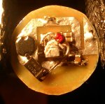
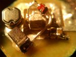
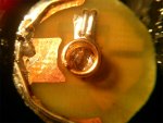
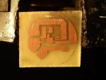
there you go my design for a constat voltage boost driver (works with extremely small external smd components!! :D) (the internal circle is a 17mm board) and I can get it even tighter but I need a better method for etching my boards..(not very sharp on the lines)
attachment.php

COMPLETED!
attachment.php


During testing which I didn't make a video of I used my dummy load as my first LOAD. It was set to the bluray setting.

I hooked it up and I got a CONSTANT 6V OUTPUT... the current started from 800mA and with the heat build-up in the rectifying diodes of the dummy load I reached 1A @ 6V
VERY GOOD, I thought!

as second load I used 2 incandescent in series... each at 5.2V giving me a total of 10.4V hungry output... the tests were somewhat satisfying ..(it could boost to that voltage but the current wasn't stable and soon the driver began to enter into protection mode limiting duty cycles...) that's not a problem I didn't design it to run to that high voltage outputs.. I just thought I should do the test :)

Now that I knew it can boost to the 6V at that current it should be no problem driving the BR diode at 600mA..

I replaced some components, retraced the paths of the feedback and I ended up with a now constat current boost driver HOORAY!:D:D
attachment.php

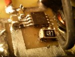
The Feedback voltage is 1.255V typical and 1.22 min for the eMSOP-8 package of the IC mine was ~1.23V

so I am stuck with big value resistors :D I used 4.7 and 3.9 in in parallel to get 2.1314ohm value.. that should give me a total of 577mA current on the output!
attachment.php


I got pretty satisfying results.. I am able to boost from 2.8V to 3.7V for a RED diode and from 3.2V to 6V for the bluray at that current

the regulation is extremely STABLE no flickerings on the output current... I don't have a scope to confirm this but when I go at my parent's house I will test it on my dad's scope!

one ODD thing happened though... Remember that when using a higher voltage input than the output requires you get into direct drive mode and out of regulation.... unless you use a buck-boost or SEPIC design... WELL check what happens in the video!!! I can't explain it... if someone can it would be nice :D I can get a higher input than the output and STILL KEEP IN REGULATION!!! with lowered current draw from the source/battery/bench PSU! I think that's awesome! :D

this time I made a video when testing... I hope you understand it:shhh:


Attachments

  • blank board.JPG
    blank board.JPG
    84.5 KB · Views: 661
  • cvBoost.JPG
    cvBoost.JPG
    98.8 KB · Views: 694
  • ccboost.JPG
    ccboost.JPG
    91.8 KB · Views: 641
  • closeupCC.JPG
    closeupCC.JPG
    112.5 KB · Views: 769
Last edited:


ped

0
Joined
Nov 25, 2008
Messages
4,889
Points
113
Re: Boost driver? Again? o_O

Nice job.

10 min vid? too long :)


Cut to the chase :D
 
Joined
Mar 29, 2011
Messages
1,056
Points
48
Re: Boost driver? Again? o_O

I have some good news and some bad news. :D

The bad news is I accidentally started the driver without load... and the open circuit instantaneously killed the regulator :( :yabbmad: note taken...

I made a new PCB with OVP (over voltage protection) and some more caps :D
Also I made it 2 layers so I can put it in my host for battery connection...

I tested it with and without load... works as a charm :D
I also put a little heatsink on top (chunck of aluminum) of the IC to keep it cooler. :)

I am very happy with it as it is. Although some professionally made PCB board would have been great :D

I didn't have a SMD Zener Diode so I used the through-hole ones :)

Some other test showed that the driver as it is CAN'T go over ~750mA and stay in regulation...

well, it's pretty enough for me and for 12x BR diode...
when I need more juice I will make a more powerful boost regulator.

:) thanks for watching :yh:

attachment.php

attachment.php

attachment.php

I put some nail polisher on the Zener to prevent shorting of the bare leads
 

Attachments

  • ovp_top.JPG
    ovp_top.JPG
    188.1 KB · Views: 582
  • ovp_angle.JPG
    ovp_angle.JPG
    210 KB · Views: 594
  • bottom.JPG
    bottom.JPG
    184.1 KB · Views: 550
Last edited:
Joined
Mar 29, 2011
Messages
1,056
Points
48
two new boards

I just spend some time on the weekend and I designed two more boards..

They can go up to 1.5A at 6V if you use 5V input! (mark this)
but since I need them from lower input like 3V and 3.6V I made them 580mA and the other one is 370mA (the output current can be set from as low as 0.01mA to 700mA) all tested even with different Inductors. They work flawlessly :)

I think I am getting good at this I might design a more powerful one in the next month or so :) for all our current hunger needs :D

they are just slightly larger than the back of the aixiz module... so they won't quite fit :D but I don't like putting them inside that thing anyway :D

these boards don't regulate if the input is higher than the output as the 1st one I made... BUT they are slightly more efficient :) I like all 3 of them .. :D

they are all protected against open output (whew) :D

here is photo:
attachment.php
 

Attachments

  • resized.JPG
    resized.JPG
    85.5 KB · Views: 569
Last edited:
Joined
Dec 17, 2010
Messages
1,144
Points
48
Wow! Nice work.

That's quite impressive. :)

Lol. Look out, Dr Lava! :crackup:
 
Joined
Mar 29, 2011
Messages
1,056
Points
48
here is a video testing one of the drivers with an oscilloscope:
(i tested all of them and they all work the same way)

at the beginning it's in off state then switched on and at the end the driver is switched off then on then off again pretty quick

what you are seeing is the voltage rise and output signal

my father was holding the battery while I was filming with :D

anyway they all show no pulsation and work pretty good and stable :)

 
Joined
Jan 21, 2010
Messages
935
Points
0
I'm going to ask a couple of probably stupid questions. Are you planning to sell these eventually? If so, how much for? And if not, can we have the schematic?
 
Joined
Mar 29, 2011
Messages
1,056
Points
48
I'm going to ask a couple of probably stupid questions. Are you planning to sell these eventually? If so, how much for? And if not, can we have the schematic?

It depends on how many people would like to have some... If there is interest I could probably make some boards...

:) I haven't decided yet what I should do with them...
Next week I will have some news about my latest driver :) It's 99% ready I just need one component replaced and final test... and it goes to the high powers :D
 
Joined
Mar 29, 2011
Messages
1,056
Points
48
Or I could post schematics.....(in deep hypnotized voice)..... :bowdown: lol :D


Top