Welcome to Laser Pointer Forums - discuss green laser pointers, blue laser pointers, and all types of lasers

LPF Donation via Stripe | LPF Donation - Other Methods

Links below open in new window

ArcticMyst Security by Avery

Cool knife edge contraption

Joined
Oct 3, 2011
Messages
899
Points
0
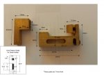
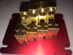
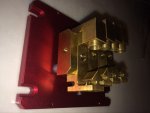
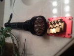
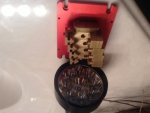
I just picked up four of these from a guy at PL. They come inside a small housing with a thick aluminum plate for the base. These assemblies are held onto a table built to be able to put a TEC under and contacting the base plate. Each of these are stacked next to each other side by side and fastened with a long bolt that goes through each one of these (through the slot at the bottom) that attaches them to the table. By slighly loosening this long bolt it allows these to slide past each other allowing a stair step configuration for mirrors, or without offset for dicros. It is infinitely adjustable here as well as the elevation of the diode holder block (up/down), and and the mirror/dicro mount works very much like a micro flex mount does. It holds a standard lens barrel like we use in all out handhelds here (threading is tighter though to allow stability in focus and beam position).

Planning to do some mixing experiments with it first and then once I get some hand held custom heat sinks made (similar to ARG's Tridentis) I plan to use these for mixing on a few handhelds. Planning on using one each on two different builds, and two of these on another. Not sure which colors I will be combining or knifing, that will be determined by the experimenting prior to gutting these out for the handhelds.

The biggest set back is they are direct press diode mounts set for 5.6mm diodes only. Once I've played with it a while I may have some machined for 9mm. Also may try to make a bezel for a 3.8mm diode to fit into a 9mm hole so I could use any of the three potentially.

It is an ambitious project but I've got time on my side. Check back someday and I will post some pics of the module in action and then eventually of a few mixing handhelds.

Thanks for looking! I mainly posted this here to have a place to refer the sink builder for pictures, and anyone else I may ask for assistance with mixing with these and building my handhelds. Hopefully some will find it interesting enough. The manufacturer of these is Edison, BTW.

Cheers!
 

Attachments

  • image.jpg
    image.jpg
    55.7 KB · Views: 366


Joined
Oct 3, 2011
Messages
899
Points
0
More pics
 

Attachments

  • image.jpg
    image.jpg
    83.8 KB · Views: 727
Last edited:
Joined
Oct 3, 2011
Messages
899
Points
0
Potential host, only one or two of the mounts would be used on a table. This host is wide enough to use the original red baseplate as the table.
 

Attachments

  • image.jpg
    image.jpg
    74.7 KB · Views: 443
Joined
Oct 3, 2011
Messages
899
Points
0
Different angle
 

Attachments

  • image.jpg
    image.jpg
    66.7 KB · Views: 244
Last edited:
Joined
Oct 3, 2011
Messages
899
Points
0
@Sigurthr- I just checked out your website, found your tube amp. Very cool. That was my big hobby before the baby came. I wish I had the time to make a website to post al of my tube amps and stuff. I have built several different tube amps including KT88, 2A3, 300B, and many others. Love the low powered SE triode the best. Great hobby, wish I still had the time for it.
 
Joined
Dec 11, 2011
Messages
4,364
Points
83
Oh nice, thanks! I love thermionic electronics! They're just too expensive for me to really get my hands into the way I want to. I'd wanted to build a tube amp for years but couldn't afford to until the parts literally fell into my lap. One day I'll make a tube tesla coil, but the filament transformer alone costs an arm and a leg!
 
Joined
Oct 3, 2011
Messages
899
Points
0
Oh nice, thanks! I love thermionic electronics! They're just too expensive for me to really get my hands into the way I want to. I'd wanted to build a tube amp for years but couldn't afford to until the parts literally fell into my lap. One day I'll make a tube tesla coil, but the filament transformer alone costs an arm and a leg!

I'm not exactly sure what your definition of expensive is but one of the best sounding tube amps I have ever built can be done very well for around $250. It's the KT88SE found at diyaudioprojects.com. It can be done even cheaper but I think a balance is struck at $250 that few other tube amps can compare to. Sourcing all the Iron from Edcor USA will take you about two months (that's their lead time) and with shipping will run about $175 last I checked. That's most of the cost, quality iron. If you ever get a chance to build this amo you will not regret it, there are several mods I have added like a three position four pole rotary switch and a couple resistors to switch the amp from triode, UL, and pentode. Another two position two pole added with a couple resistors thrown in parallel to the cathode bias resistor allows you to run the lower rated 6L6 and similar. I added an extra 30h choke in my power supply instead of a resistor to further smooth out ripple to the gain stage. I still have my copy of the schematics I made from this design I am willing to share with anyone who wants it. It will be the most fun and best sounding 18wpc you'll ever build.
 

ARG

0
Joined
Feb 27, 2011
Messages
6,772
Points
113
Edison does good work, those modules are great!

(similar to ARG's Tridentis)
I have done multidiode lasers, but the Tridentis was done by CDBeam :)

A good way to get a smaller beam with these moduels is to knife edge in two pairs, then combine the pairs with a PBS cube, though there may not be enough space for that.

Good luck! :D
 
Joined
Feb 25, 2010
Messages
1,643
Points
113
Interesting...Very interesting...Looks like Edison has a great product...

MMmmmmm ???? But....when using the P73.....one MUST have the ability to translate the LD up/down-Left/right...WITH respect to the 2mm EFL collimation lens.

While providing great adjustability for all other movements....this unit does not offer that...SOOoooo....the take away is that this is great for ALL other LD's....except the P-73....IMNSHO. For THAT LD...the adjustable LD mount and a stand alone Flexmount is still the only option....to facilitate Optical Correction !!

Good Luck !!! Post Build Pics !!! Combiners Rule !!!!

Lite'em Up CDBEAM=======>
 
Joined
Oct 3, 2011
Messages
899
Points
0
ARG and CDBEAM, sincerely sorry about the mixup there. I hate to give away someone else's credit and not give credit where credit is due.

@CD- I'm not exactly sure what the issue is with the P73 that requires the adjustment you discussed. Can you elaborate a little more? If X is the axis of the light through the lens, are you saying you need Y and Z axis adjustability on the lens (or diode with respect to the lens) to combine with the P73? Why is this and not with other diodes? I am new to knife edging and combining so please bear with me.

Another thing about these particular modules is the diodes being direct press requires some very precise alignment with respect to rotation around the fast and slow axis of a multimode before you press the diode in. If you're trying to stack a multimode beam well the diode must be pressed in perfectly aligned. Bearing all this in mind I think this is best used for single mode combining.

I am going to see if Mrcrouse can machine me a couple of the L shaped diode blocks with a 12mm hole. Granted the whole thing is only 11mm wide so that will mean the only use I will get from that would be using it "solo" for a handheld. I guess I could put some shims between the bodies of the other part and still stack them side by side too.

My intentions when buying this was to have a nice platform to learn how to combine and knife edge, and once mastered (well, mastered is a strong word) to strip these modules out and use them to make a Tridentis like handheld. At $50 a piece (not considering the nice casing they came in) I thought they were a pretty good deal when compared to building with separate parts. Those little flex mounts are $20 by themselves.

Hopefully I will have some time next week to play with some LPC826 and SJO6 405's I have laying around. That will be my first combination. I may add one of the new 520's (lowest mW made) I have as well and see what interesting results I get. I've got some adjustable drivers for all these diodes so I will have some ability to do some real color mixing, can't wait to see how this works!

Thanks for everyone's input. Stay posted if your interested to see how well I can make these work.
 
Joined
Feb 25, 2010
Messages
1,643
Points
113
@CD- I'm not exactly sure what the issue is with the P73 that requires the adjustment you discussed. Can you elaborate a little more? If X is the axis of the light through the lens, are you saying you need Y and Z axis adjustability on the lens (or diode with respect to the lens) to combine with the P73? Why is this and not with other diodes? I am new to knife edging and combining so please bear with me.

Another thing about these particular modules is the diodes being direct press requires some very precise alignment with respect to rotation around the fast and slow axis of a multimode before you press the diode in. If you're trying to stack a multimode beam well the diode must be pressed in perfectly aligned. Bearing all this in mind I think this is best used for single mode combining.

JD....To optically correct the P-73....One must use a VERY short EFL lens. That is the only way we have found it to be possible. SOOoooo ...a 2mm EFL Collimation lens is used. The downside of this is that the propagation axis of the LD MUST be precisely presented to the 2mm Collimation lens. This means that the beam path MUST me dead centre / spot on with respect to the Collimation lens.

OK....so....this then demands that either the LD is X-Y adjustable in its mount....or the lens is X-Y adjustable. I have trialed both....but the simplest is the LSP adjustable mount design.

In this mount...the LD can be adjusted...up/down....left/right....within the mount....and the geometry ( Axis alignment) BETWEEN the LD and the Collimation lens can be precisely set.

This optical set up is just what it takes to optically correct the P-73 beam.
The reason this is so with the P-73...and not so much with the Multi-element 445's....is that the initial die output has MUCH greater astigmatism ( Line like)

Even after using an adjustable mount....the P-73 beam must be sent thru a set of Cylinderical lenses....to further correct the beam !!@ See my post on the Optical correction of the P-73 in a HH format.

And finally....YES...Radial position/orientation of the LD...when employing knife edging MUST also be considered !!! No doubt that intimate contact achieved by pressing the LD into a module should provide the best thermal transfer....But...to knife edge...or use a PBS....Radial position/orientation must be set a specific direction. The LD mount design must have this adjustability. Pressing in the LD limits that adjustability.

Again...there are always trade-offs !!! :san::san::san:

Good luck....keep us posted !!

Lite'em UP CDBEAM=======>
 
Joined
Oct 3, 2011
Messages
899
Points
0
Going to spend a little time on this today. Going to start simple with three diodes, two LPC826 and an M140. Going to try to set it up where the stack on the knife edged LPC's corresponds to the fast/slow axis of the M140 so the two stacked beams will "fill" most of the line or bar shaped beam the M140 creates. I will be running the two LPC's around 300mW each using some simple linear drivers. I will use my bench top PSU to dial up the M140 to get the best power combination for the 600mW of red. I should have this done by the end of the day if all goes as planned. Stay tuned for a couple pics late tonight.
 
Joined
Feb 25, 2010
Messages
1,643
Points
113
Going to spend a little time on this today. Going to start simple with three diodes, two LPC826 and an M140. Going to try to set it up where the stack on the knife edged LPC's corresponds to the fast/slow axis of the M140 so the two stacked beams will "fill" most of the line or bar shaped beam the M140 creates. I will be running the two LPC's around 300mW each using some simple linear drivers. I will use my bench top PSU to dial up the M140 to get the best power combination for the 600mW of red. I should have this done by the end of the day if all goes as planned. Stay tuned for a couple pics late tonight.

Maybe you already know the info below....maybe not.....in any case....another member may find this useful !

OK...I would select the M140 as my main beam....and set it as the 2nd module in the three stack line up. The 826's could be called the secondary beams.....and they would be 1st and 3rd in the line up

The M140 beam geometry....as it exits out its collimation lens....is a slight bar/rectangle. It would be best to position the bar geometry of the M140 so that the bar is like this l NOT like this --

In this way....as the beam strikes the mirror, it is bounced 90 deg....and continues to look like this l

NEARFIELD ADJUSTMENTS

These adjustments are accomplished by observing the beam path.....and the mirror surface on the knife edge's.

Now....the beam from the 1st 826 SHOULD pass right by the edge of the M140 knife edge mirror. Adjust this beam as CLOSE as you can to the edge of the mirror.....but still allowing 95% of the beam to pass by. The adjustment looks like it can be accomplished by moving the mirror mount head... in and out along the slide track....then locked down when you get the best position.

M140 beam, being the main beam....should not need adjustment on the mirror head mount......as the secondary beams should defer to the main beam.

So.....we now have the 1st and 2nd beam nearfield as close as possible.....but yet.....still allowing one beam to join the next beam with a minimal loss of optical power.

Next....we add the 3rd secondary 826 beam. The mirror head for this third unit will also require in-out adjustment of the head. Again....the goal is to bring this beam as close as possible to the 1st and 2nd beams.

I think what you will see about 6" ( 150mm) from the stackage front is something that looks like this

olo

with the one l being 445 blue...........
and the two o being 650 red nm

I think this may be the best set up....Dunno 4 sure !!!

NOW.....

FARFIELD ADJUSTMENTS

The very small adjustment bolts on the mirror mount heads will be used for the Farfield adjustments. Place a white target about 25' (7.6M) away from you stackage.

I would adjust the 2nd mirror mount head (blue-Master) for up and down....Pitch. Depends on how detailed you want to be.....but let's say you want the beam propagations parallel from your optical plane.....SOooooo....if the stackage unit is on a work bench 40 " (1M) off the ground....at 25' (7.6M) away....that beam should hit a mark of 40" (1M) off the ground.

The Pitch of the other beams, the 1st and 3rd secondary should ALSO be at THAT elevation. There are Pitch adjustment bolts to accomplish this alignment.

Next....the YAW....or left to right Farfield adjustment.
For this set-up....I would again start with the 2nd/Master beam. It would seem logical to want the 2nd beam line to be parallel with the stackage footprint geometry. To that end....I would adjust the YAW bolt on the Master unit to accomplish this end.

Again....the YAW adjustments of the 1st and 3rd beams should follow and be aligned to the Master (2nd) beam. You will use the YAW bolt to accomplish this alignment.

Take your time !!!!!! It is a somewhat demanding process....BUT....the result is BEAUTIFUL !!!

At the end of the day.....at 25' (7.6M) away.....you would want to see this

olo

pattern/geometry on your Farfield target.

Hope this helps. :san::san::san:

Lite'em Up CDBEAM=======>


Top