Welcome to Laser Pointer Forums - discuss green laser pointers, blue laser pointers, and all types of lasers

LPF Donation via Stripe | LPF Donation - Other Methods

Links below open in new window

ArcticMyst Security by Avery

CNI GLP-589 issues

Joined
Sep 22, 2010
Messages
1,358
Points
48
Last night I was going to take some pics of my 589 CNI GLP and my 594 HeNe together and the 589 stopped working. As always I warmed the module end up by holding it in my hand for a minute or so (this laser never like to lase at ambient room temp) and it fired right up. I turned it off, unscrewed the battery cap a bit so I could tape the switch down for the pics but when I tightened the battery cap nothing happened. I thought maybe the battery was dead because typically it'll lase for a few seconds then turn off if it needs a recharge but swapping batteries did nothing. The battery shows 3.55v which is easily enough to power it.

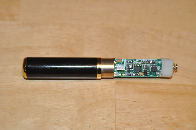
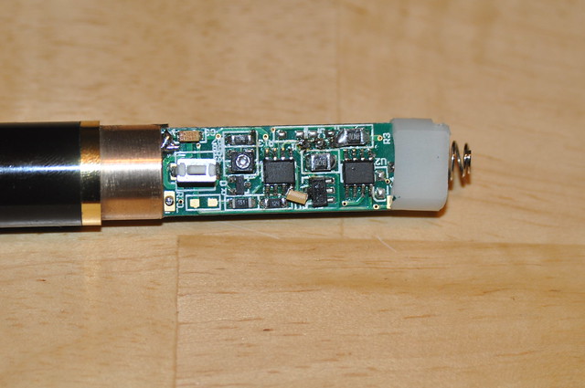
Then things when from bad to possibly worse. The rubber boot over the switch has always tended to stick a bit but never been that big of a deal and has always been fixable but a slight twist of the battery barrel. I noticed last night that the battery barrel had separated from the gold ring that separates the battery and driver compartment from the module end by between an 1/8th and 1/4 inch. Somehow I managed to twist the damned barrel when i went to push it back together and got the rubber boot entirely out of place. After realizing getting it back in place the way it was would be impossible I decided to just remove the lower barrel so I could look at the driver. After working it for quite awhile I finally got it to come apart. I was afraid I damaged the switch yanking it apart since the rubber boot was wedged against it but a quick continuity test showed it was fine. Looking at the driver nothing looks toasted.

That all said does anyone with experience with these lasers have any suggestions on where to start troubleshooting? I'm going to dig out my bench supply so I can power it without needing 4 hands to hold the battery and jumper wire in place while testing it. The only thing I can think of is to see if there's continuity across the diode but after that I'm lost with drivers like this.


Joined
Jan 8, 2009
Messages
3,145
Points
83
I'm wondering if the spring folded over and touched the case when you put in the cell the rubber boot could have caused this.
 
Joined
Feb 1, 2008
Messages
2,894
Points
0
Get that driver on a bench supply and make sure the laser either works, or doesn't. We can start from there.

Also, get as many photos of the situation as you can - this will help us help you sort this out. I doesn't sound like a disaster, but for this one we should do it right. This is no $10 green module.
 
Joined
Sep 22, 2010
Messages
1,358
Points
48
Get that driver on a bench supply and make sure the laser either works, or doesn't. We can start from there.

Also, get as many photos of the situation as you can - this will help us help you sort this out. I doesn't sound like a disaster, but for this one we should do it right. This is no $10 green module.

No kidding on the $10 module part. It's only the 1mw model but it still cost a couple Benjamins. I didn't have time to hook it up tonight. After pulling a 6 day run at work my ass was dragging and all I did was veg in front of the computer numbing my brain with minecraft. Tomorrow after work I'll hook it up and see what's going on. I found the thread where I had posted some measurements of its power draw while powered off my bench supply so I know what power/current levels are safe. I'll get some good pics too since I already have the DSLR on the tripod in preparation for taking pics of the aforementioned lasers one of which is very familiar to you. ;)
 
Joined
Sep 22, 2010
Messages
1,358
Points
48
Ok I finally had time to get the bench supply out and the results weren't what I was hoping for. Set at 3.6v the driver was pulling a steady .83A which is only slightly less than the .84A when I tested it a year or so ago. I suspect maybe the diode died because before when it wasn't warmed up enough if you looked in the aperture you could could see the red of the IR diode through the filter. If it is the diode I don't even want to think bout replacing it since the crystals would likely have to be realigned. If it comes to diode replacement I'll have to send it somewhere (laserglow maybe?) and have them do it which will probably cost more than I paid for the laser to start with.

Here's a few pics of the laser and driver with the back barrel off. For some reason my camera did not want to focus on the bottom side of the driver board. I can try again tomorrow if you need better ones.


2012-09-16_08-32-28pm by ltkernelpanic, on Flickr


2012-09-16_08-32-54pm by ltkernelpanic, on Flickr


2012-09-16_08-37-50pm-c by ltkernelpanic, on Flickr

Full size can be seen on flickr.
 

Hiemal

0
Joined
Dec 27, 2011
Messages
1,443
Points
63
At any point did you accidentally hit it against something while you were taking it apart?

If you did, the crystals could have been dealigned, or you could have also killed the laser diode, too. If not, then it seems awfully strange for the diode to just, die, like that. I'm taking a guess to say that these modules run the IR diode right at or below their rated power, to help prevent early death, but... maybe they don't?

I don't know, that's my take on it anyway!

If, by chance, you don't get it working again, could I maybe buy the broken module off of you? :eek:
 
Joined
Sep 22, 2010
Messages
1,358
Points
48
No. I was holding it in mid air when it stopped working. The only thing I can think of is it shorted when I loosened the battery cap but that seems highly unlikely as there's nothing for it to short to. Sadly I think it's the diode because like I said before when the crystals were below lasing temp I could see the red of the IR diode through the IR filter. I may contact laserglow as they're a CNI dealer and ask for a repair quote.
 
Joined
Feb 1, 2008
Messages
2,894
Points
0
Don't give up on it yet. We just saw the picts tonight.

Bringing the first photo to full screen - its still not clear enough. There is a cluster of resistors or solder joints above and between the two visible ICs. It looks like discoloration from here, but I can't be sure what's going on there. Does anything look chemically "altered" on there from what a clean circuit board should look like?

Go ahead and do this for me,

Get out your cheap webcam or a cell phone camera without an IR filter. (You can make sure it doesn't have an IR filter by trying to view the IR led output of a working remote control for a TV or a radio) Power the driver, and look for any IR light that is emitted from the module BUT do this only by looking at the camera LCD or webcam's computer screen program.

Keep that possible IR light out of your eyes when pointing the aperture towards the camera.

589s uses different lasing wavelengths than a 532nm pen does, so if the different coatings don't allow it, there might not be much visibly dim IR to view. The coatings on those crystals are VERY good on the yellow arrangements. - very wavelength picky. They might do a nice job of filtering the NIR.

Do you see any white light through the camera? Is the white light steady? Intermittent? Continuous? Smooth? Does it change in brightness over time? Is there anything there at all?
 
Joined
Sep 22, 2010
Messages
1,358
Points
48
Sorry about the pics. Usually I get nice clear pics from my D90 but those came out like ass. I reshot them using my 50/1.8 instead of my usual 28-200 walk around lens.


I tried using my iPhone to look for any signs of IR and didn't get anything. My Harmony remote lit up bright white when I used it as a reference. Looking at the area you pointed out with a bright light the discoloration looks like it's just flux residue where the leads from the big multi-turn pot on the other side comes through the board and is soldered.

Here's some much better pis. You can view the full size of the 100% crop on Flickr.


2012-09-17_09-53-05pm by ltkernelpanic, on Flickr


2012-09-17_09-54-49pm - Version 2 by ltkernelpanic, on Flickr
 
Joined
Sep 16, 2007
Messages
3,658
Points
113
These CNI modules are IR filtered. Their filters are good, too. Also... I think iPhones have IR filters as well. My gf has one and I'm pretty sure I once tried using it to test for IR on a known working laser.

It looks like there is a burn on the switch side of the driver. Can you confirm this?

Sorry about your laser. These are pretty nice pointers, too. 589nm is badass.

I'll leave the help to the guys who know electronics. Good luck! :)
 
Last edited:
Joined
Sep 22, 2010
Messages
1,358
Points
48
If she has an iPhone 4s it might be it might be IR filtered since the camera and optics are vastly improved in it over the older iPhones it but my 4 definitely is not. Those marks that look like scorch marks looked like flux residue to me when I looked at it. That's right where the legs of the big blue adjustment pot are soldered. I thought I had a bottle of 93% isopropyl alcohol at home but it looks like I'm out so I'll grab a bottle at work tomorrow and see if it comes off.
 
Joined
Sep 22, 2010
Messages
1,358
Points
48
Hate to bump this again but I hate having a $300 laser in pieces. Any ideas/advice would be appreciated.
 

ARG

0
Joined
Feb 27, 2011
Messages
6,772
Points
113
Can the module be unscrewed into individual pieces like the green can? Or is it all sealed up because the crystals oxidise?
If you can open it up, maybe you can get a petter look at the diode to see if it's making any IR.
 
Joined
Sep 12, 2007
Messages
9,399
Points
113
^It uses the same crystals as a green. Just different coatings.

Do I see a tantalum bodged on between that IC and SOT-223? Is that supposed to be there? I expect better from CNI.

If it's drawing the appropriate current, that probably means alignment issue, crystal degradation, or dead diode. Probably one of the first two - I'd send it in for repair.
 

ARG

0
Joined
Feb 27, 2011
Messages
6,772
Points
113
^It uses the same crystals as a green. Just different coatings.

Do I see a tantalum bodged on between that IC and SOT-223? Is that supposed to be there? I expect better from CNI.

If it's drawing the appropriate current, that probably means alignment issue, crystal degradation, or dead diode. Probably one of the first two - I'd send it in for repair.

Interesting, I did not know that. I only knew that the process was similar to 532nm.

If you don't want to go through the trouble of sending them in JLSE is buying all the dead 589nm GLP's.
http://laserpointerforums.com/f39/looking-buy-trade-your-old-not-working-589s-67803.html

Also look through this thread if you haven't already:
http://laserpointerforums.com/f40/trying-resurrect-cni-589nm-pointer-66467.html

It seems like the GLP's are not very reliable.
 
Joined
Sep 22, 2010
Messages
1,358
Points
48
Whoops. I wrote this last night and forgot to hit the post button. Anyways...

Thanks for the posts guys. Yeah that cap was there when I took the laser apart. You can see it in 589 repair thread too. You can also see the flux residue as well.

The driver seems to be fine. When I tested it with my bench supply about a year ago and again last week it pulled the same .83-.84A.

I guess the only thing left to do is try to getting the module out and see if I can see if I can tell if the diode is still good or what. Even if I can see the bond wires are toast I don't think I'd have the knowledge or skill to replace the diode.


Top