Welcome to Laser Pointer Forums - discuss green laser pointers, blue laser pointers, and all types of lasers

LPF Donation via Stripe | LPF Donation - Other Methods

Links below open in new window

ArcticMyst Security by Avery

Capacitor question

Joined
Mar 8, 2008
Messages
2,669
Points
48
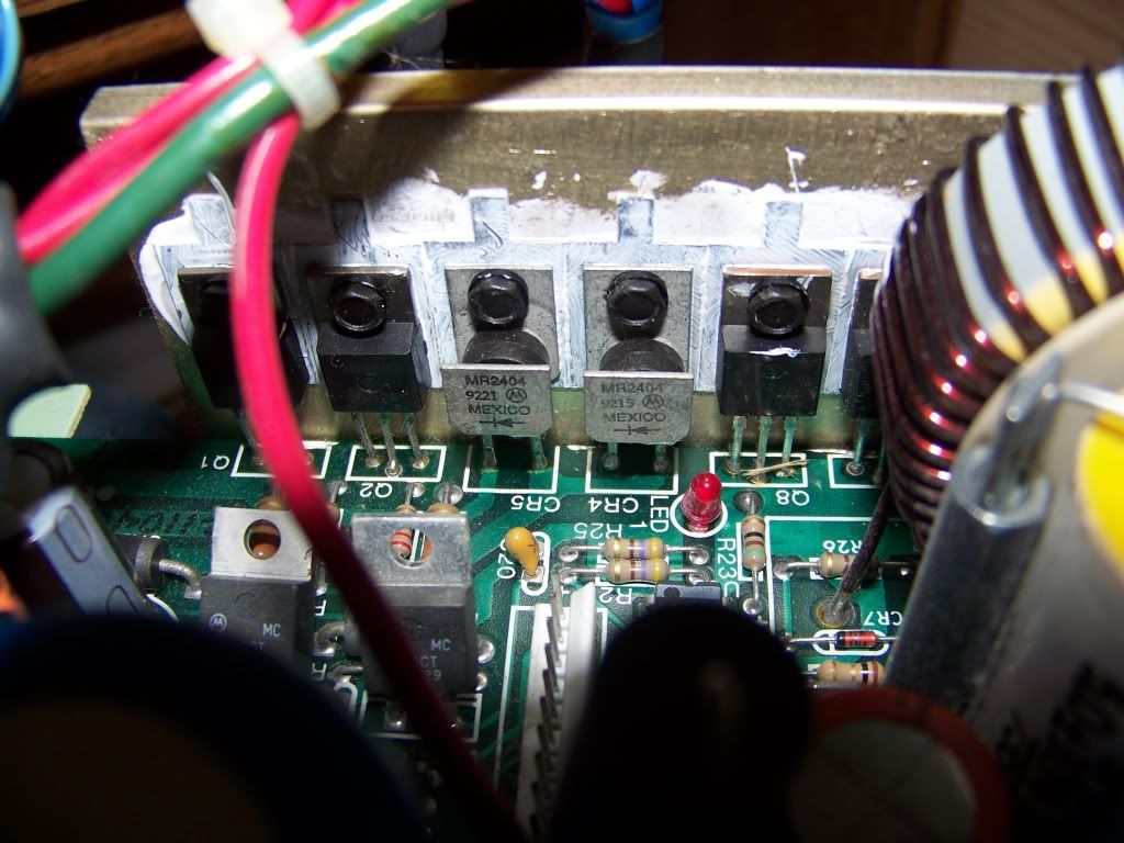
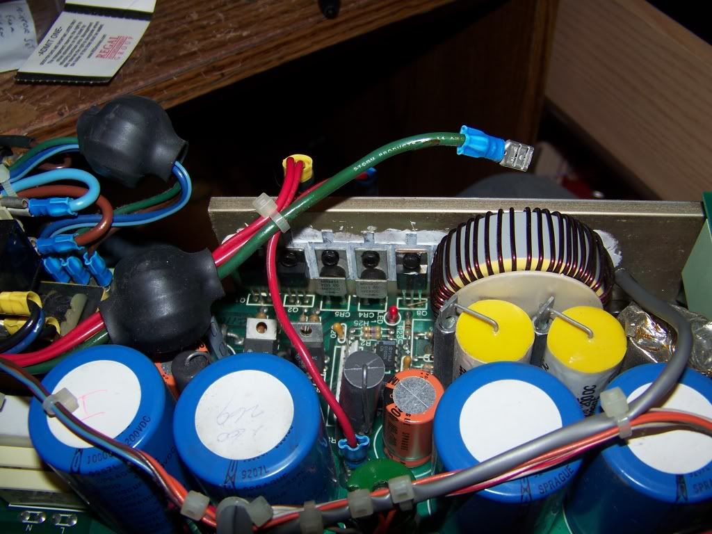
Ok, so as some of you may know I'm trying to track down a short in the PSU of one of my Argon lasers.

SOOO... I have it narrowed down to a capacitor that is acting funny. Normally when I tested resistance across all the other capacitors, it started with a fairly low resistance which got higher as the meter pumped electricity into it. But this one is being a bit weird. When I try to test resistance across the capacitor in question, I get nothing. Not 'nothing' as in 0ohm, but nothing as in the meter sees it as an open circuit.

So my question is: While my meter see's this as an open circuit, the meter only uses MAYBE 6v when measuring resistance. This capacitor normally sees upwards of 150VAC (basically straight from the wall). Could an 'open circuit' at 6v actually be a short at 150V? Is this a typical failure mode of capacitors?

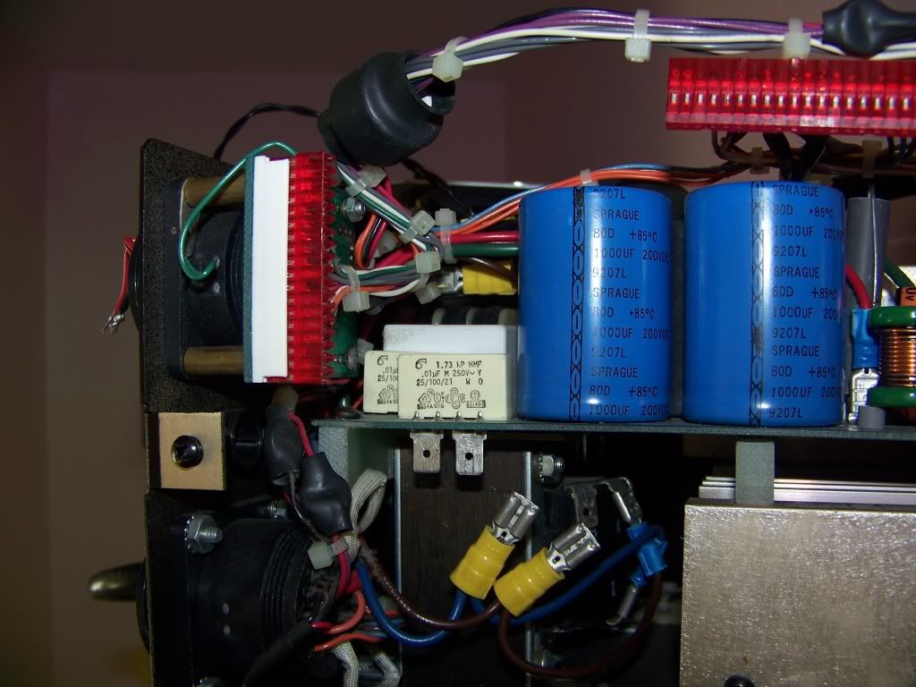
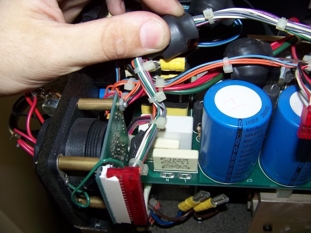
I'm not sure what kind of caps they are, but here is a picture for reference. The cap in question is the white one right in front, which you can see all the information on.

000_0623.jpg


000_0626.jpg


Thanks!!
GG


rkcstr

0
Joined
Dec 1, 2007
Messages
1,368
Points
0
I can't really tell in the picture (I don't think I see any), but is the top popped up at all on the "bad" cap?  That's typical for a failed electrolytic capacitor.
 
Joined
Jul 27, 2007
Messages
3,642
Points
63
i don't think you should be getting an open reading - but the only true way to tell if it has failed or not is to test it with a meter that can measure capacitance (I've already used mine to diagnose my friend's central air conditioning system - the fan would stop working when hot because the fan's run capacitor went bad)
 
Joined
Mar 8, 2008
Messages
2,669
Points
48
I'll try to test capacitance, but doesn't it need to complete a circuit to do that? I'll try to wire it in parallel with a 9v battery and see if any voltage even makes it through.

And another question, does anyone know where I can get another capacitor which is the same size? Or do you think that would be pretty hard to find?
 
Joined
Jan 7, 2007
Messages
6,309
Points
83
If it measures different than the others, it is a starting point. I presume it is in the primary circuit as we discussed. A diode and the power line may tell you something but it appears open but at 9 volts ....... Hard to tell what that would do to the circuit.
DigiKey may have something similar.

Mike
 

Hodad

0
Joined
Jul 13, 2008
Messages
67
Points
0
I believe that cap is a type of HV ceramic cap, with a very low capacitance. You won't be able to read anything but an "open circuit" with a meter set to resistance because it will charge too fast for the meter to pick it up.

Your idea with the 9v battery might work, if you removed the cap from the circuit, though you would have to charge it with the battery, then connect the cap to your meter set to a low DC voltage range - you might briefly see the voltage go up then quickly back down.
 
Joined
Mar 8, 2008
Messages
2,669
Points
48
rkcstr said:
At Mouser.com:

http://www.mouser.com/Search/ProductDetail.aspx?qs=gd1H9TFaAAF3%2b6C8RNIBxw==

Or, this place has em cheaper, but they also have $20 min. order:

http://www.apexjr.com/capacitorsR.html


Either way, make sure they'll fit in place of the old ones.


Also, most capacitance meters you just measure across the cap... but most have an upper limit of range somewhere around 100uf, I think.

Rkcstr, thanks for the link! Unfortunately I'm looking for a match to the white 'box style' ones.

Mike, do you know how EXACT the match needs to be for these caps? Yes they are on the line side, and I think the cap in question is the second or 3rd component on the AC side, so it takes the brunt of it! I found these, which appear to have the same ratings. It sure is hard to find these kind of caps rated for AC.... Here's a link, think these would be ok?

http://cgi.ebay.com/Y2-Film-SAFETY-...Item?_trksid=p3286.m20.l1116#ebayphotohosting
 
Joined
Mar 8, 2008
Messages
2,669
Points
48
Hodad said:
I believe that cap is a type of HV ceramic cap, with a very low capacitance.  You won't be able to read anything but an "open circuit" with a meter set to resistance because it will charge too fast for the meter to pick it up.  

Your idea with the 9v battery might work, if you removed the cap from the circuit, though you would have to charge it with the battery, then connect the cap to your meter set to a low DC voltage range - you might briefly see the voltage go up then quickly back down.

Hodad, there are several of these types of caps on the board, and they all give me a measurement except for this one :(

I've done some looking around, and they are poly film capacitors. Used for high rate pulsing or line filtering (like in switching power supplies, such as this). This one is meadium sized compared to the other white 'box-style' capacitors. Even the bigger and smaller (and even ones with the same ratings) still give me a measurement :(
 
Joined
Aug 15, 2007
Messages
1,880
Points
0
Those ones look perfect. Good luck :)
For future reference, caps usually need the exact same capacitance (uF or mFd) rating, and equivalent or higher voltage rating.
 
Joined
Mar 8, 2008
Messages
2,669
Points
48
I think I've found something a bit more interesting than a cap that measures funky. Maybe Mike can chime in on this one as well... But I had a chance to measure the main rectifiers which are bolted and heat-sinked to the huge metal heat sink in the power supply. On one of them, I am measuring a 'short' across it, but I dont know if it's supposed to be that way or what. I tried putting the DMM leads both ways in case I just had them on wrong, but it registers 1ohm or less either way. I'm guessing it shouldn't be like this... but who knows. Laser builders are pretty wacky. Here is a picture of what I'm talking about, it is the diode on the RIGHT (CR4), just to the left of the little LED. The one on the LEFT, measures 50+Ohm.

000_0630.jpg


000_0631.jpg


EDIT: In the picture it looks like theres a piece of *something* that could be shorting two pins of Q8 together, but it's just a little piece of debris that I dropped in there on accident. Forgot to clear it for the pictures  :p
 
Joined
Jan 7, 2007
Messages
6,309
Points
83
That part of the PS looks like mine. I wonder why only two diodes. You need 4 for full wave rectification and the voltage rating on the caps isn't enough for a voltage doubler circuit. The 1 ohm reading is unusual since most diodes don't read that low with an ohmeter. Those diodes are big enough to be in the main supply -- looks hard to remove to check out of circuit. Also look for a short in the circuit connected to the diode.

Too late for me here. Niteall -------

Mike
 
Joined
Mar 8, 2008
Messages
2,669
Points
48
Hemlock Mike said:
That part of the PS looks like mine.  I wonder why only two diodes.  You need 4 for full wave rectification and the voltage rating on the caps isn't enough for a voltage doubler circuit.  The 1 ohm reading is unusual since most diodes don't read that low with an ohmeter.  Those diodes are big enough to be in the main supply -- looks hard to remove to check out of circuit.  Also look for a short in the circuit connected to the diode.

Too late for me here.  Niteall -------

Mike

there are two more diodes behind that big toroid ring, just cant see them in the picture :-[

the other diode, which has the EXACT same model number, reads above 50 ohm. It wouldn't be too hard to remove to test. And by the 'circuit connected to the diode' do you just mean the components before/after the diode?
 

rkcstr

0
Joined
Dec 1, 2007
Messages
1,368
Points
0
Sorry, I thought you were talking about the large electrolytic caps earlier  :-[

Now I see you were talking about the smaller ones.  Those actually are what I believe are caps across the AC in, I think they're for noise supression.  I doubt they'd go bad, and you probably have a different problem... which I see you're talking about now.

As for the diodes (or transistors), they should only pass current in one direction, so if you measure low resistance in both directions, something's up... BUT, that is for OUT of circuit since there may be something else shorting it in the circuit.  If you suspect one, it would be best to remove it to test, though it looks like that may be difficult.

Though, I'm not sure the rectifiers going bad is very common... ?
 
L

laserguys

Guest
I think you found your problem..
If all the similar diodes measure the same except the CR4....
then I'd bet the CR4 diode is gone (shorted out).
Take it out and test it on the bench. :)
 
Joined
Mar 8, 2008
Messages
2,669
Points
48
I'll order a new diode (god knows it will be easier to find than those white caps!!) ASAP and swap it in. It really isn't too hard to get out of there, its just bolted on a heat sink with some dielectric grease  :)

Oh, and I know it was posted above but I just want to make sure.... These rectifier diodes should only pass current in one direction, right? If so, I'll just pull it out tonight and give it a test on a simple circuit to see what I get.


Top