Welcome to Laser Pointer Forums - discuss green laser pointers, blue laser pointers, and all types of lasers

LPF Donation via Stripe | LPF Donation - Other Methods

Links below open in new window

ArcticMyst Security by Avery

Can anyone see what I've done wrong?

Joined
Jan 20, 2008
Messages
1,724
Points
0
I swear this whole whitefusion build is cursed. I've blown almost $200 worth of diodes while making this, now I've rebuilt this driver twice and each time it's putting out 2+ amps. I've built dozens of drivers before, and I've never had a problem anything like this before.

Can anyone spot what I'm doing wrong here? I'm measuring 50ohms between the out and adj pins of the regulator, so in theory I should be getting a just a couple mA, but instead it's putting out enough amperage to make my test load too hot to touch.

 
Last edited:


Joined
Nov 22, 2008
Messages
1,506
Points
48
Can't see anything wrong - I presume there are 2 other pots wired the same way hidden by the heatsinks? Try cutting +v to the other regulators, and see if each regulator works fine independently of the others.
 
Joined
Jan 7, 2007
Messages
6,309
Points
83
When this loses regulation, is it connected to the diodes? Did you remember (and test) that the green is reverse polarity?

HMike
 

aXit

0
Joined
Sep 15, 2009
Messages
206
Points
0
I would highly recommend not measuring resistance with the pot already in circuit. Unless you have a special low voltage ohms measurement on your meter, current through the chip itself is severely skewing your reading.

If you have a test load and a DMM, then just adjust the pot until the current is correct, ignore the resistance when it's already in circuit.
 
Joined
Sep 20, 2008
Messages
17,622
Points
113
Hard to tell by the photos... do you have a schematic/drawing of
exactly what you put together (not a generic DDL drawing... but
your exact circuit in the pictures)

Like CB posted... disconnect the other regulators and take it down to
one basic circuit. Check for small solder jumpers or frayed wire shorts..
Some times a small short is found under overheated flux... scrape
between pads to be sure.. Are the Heatsinks common electrically ??

Jerry
 
Joined
Jan 20, 2008
Messages
1,724
Points
0
Can't see anything wrong - I presume there are 2 other pots wired the same way hidden by the heatsinks? Try cutting +v to the other regulators, and see if each regulator works fine independently of the others.
I'll give that a shot, but I can't imagine how that would make a difference, the drivers are isolated from eachother, they just share a common 12v rail.


When this loses regulation, is it connected to the diodes? Did you remember (and test) that the green is reverse polarity?
HMike
Using a test load, no diodes here. Yes, I've checked that my test load works, isn't shorted out or anything, etc... I'm not sure what the amperage is, but it's awfully high. My DMM is set to the 2v range, and it maxes out, so it's obviously more than 2A... Within a second the diodes on the test load are too hot to touch.
 
Joined
Jan 20, 2008
Messages
1,724
Points
0
I would highly recommend not measuring resistance with the pot already in circuit.
I haven't touched the pots really, they're set to the default resistance they came with from the factory, which is around 50ohms. I was just pointing that out to clarify that I wasn't setting the pot to its lowest setting or something.

Hard to tell by the photos... do you have a schematic/drawing of
exactly what you put together (not a generic DDL drawing... but
your exact circuit in the pictures)
In the second picture I've drawn some lines to clarify what's going on. I could make a drawing, but it'd basically just come out as a standard DDL circuit.
The heatsinks are isolated.
 
Joined
Nov 22, 2008
Messages
1,506
Points
48
Are the Heatsinks common electrically ??

^^This is a possible option which would be solved/noticeable by cutting power to the other regulators. If you're powering up the other 2 regulators without a load, they essentially just up the voltage to the highest output possible, which is Vin - 2.25v I think.

EDIT: already answered, ignore this.
 
Joined
Jan 7, 2007
Messages
6,309
Points
83
Jerry ---
Would a parasitic oscillation be possible with these stacked like this? No common ground. I've seen 7805's go nuts without proper bypassing. Have you experienced this?

A wild ass guess here--------

HMike
 
Last edited:
Joined
Sep 20, 2008
Messages
17,622
Points
113
If the outputs are really isolated and all 3 adjustment pins are isolated
and the only common pin is the input line I can't see any cause for oscillation problems Mike...
Perhaps the Regulator it's self had been damaged... and is outputting
full current/voltage...
Would need to be checked with a DMM as well as the Reference Voltage...

Like CB stated... disconnect all 3 regulator circuits and go at them one by
one... don't take anything for granted...

Jerry
 
Joined
Jan 20, 2008
Messages
1,724
Points
0
Tried one by itself, no change. Bah.

The amperage is the same as the input, the voltage is dropped by 1.5v or so.. I can only assume the regulators are dead. I'll try swapping them **AGAIN** later this evening... I dunno, maybe I put reverse current to them at some point or maybe I ESD'd into them.

*Sigh*...
 
Joined
Apr 29, 2008
Messages
1,562
Points
48
Your circuit is incorrect. Refer to this rather simplistic diagram for the operation of the LM317 regulator:
LM317%20basic.jpg

Your V-Out needs to be continuous with the ADJ pin of the LM317. With your setup it is continuous with the OUT pin.
 
Joined
Nov 22, 2008
Messages
1,506
Points
48
Your circuit is incorrect. Refer to this rather simplistic diagram for the operation of the LM317 regulator:
LM317%20basic.jpg

Your V-Out needs to be continuous with the ADJ pin of the LM317. With your setup it is continuous with the OUT pin.

This!! Move output to the other side of the resistor and it should be solved.

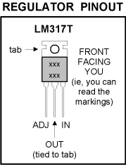
lm-317-pinout.gif
 
Joined
Jan 20, 2008
Messages
1,724
Points
0
Your circuit is incorrect. Refer to this rather simplistic diagram for the operation of the LM317 regulator:

Your V-Out needs to be continuous with the ADJ pin of the LM317. With your setup it is continuous with the OUT pin.

THANK YOU!!

I knew it was something stupidly simple like that... I just needed another set of eyes to figure it out.
 
Joined
Jan 7, 2007
Messages
6,309
Points
83
Way to go Jimmy ----
I had my glasses off and my nose to the screen but I didn't see that. I think I see what you say ....

HMike


Top