Bluefan
0
- Joined
- Aug 15, 2009
- Messages
- 1,443
- Points
- 48
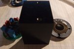
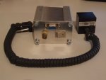
I've been busy a few weeks back, building a lpm using an ophir head I got. I bought 6 heads of which only one had an undamaged coating. I plan to recoat the 5 and build an lpm with the 6th. It has 1mW resolution, around 1 sec risetime and a max of 5W.
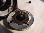
These ophir OEM heads are really easy to work with, all the amplification is done on the boards. Adustments for the gain and offset are accesible at the back of the sensor. The sensor disk itself is pretty nice to see, the radially distributed thermocouples are directly on the metal sensor disk (The photos of the opened thermopile head are of a head that needed a recoating).
The heat generated by the laser heats up the central part of the disk. The outside part of the disk is in good contact with the case. The thermocouples run between these area's.
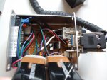
The part number is identical to the 20C-A-1-Y head and the output is 1mV/1mW. Only the offset required a bit of adjustment, but this may be because of the supply voltage of +/- 9V.
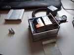
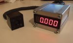
The readout is just a good panel meter powered by a 7805. Two 9V batteries provide the power for the ophir head and the readout. I put a BNC output at the back so that I can connect it to other measurement devices. Making this readout really was very easy but fun to do none the less. And because of the size it's sort of handheld. If anyone also has an ophir head and wants to build a lpm feel free to ask anything, I'll share what I know.
These ophir OEM heads are really easy to work with, all the amplification is done on the boards. Adustments for the gain and offset are accesible at the back of the sensor. The sensor disk itself is pretty nice to see, the radially distributed thermocouples are directly on the metal sensor disk (The photos of the opened thermopile head are of a head that needed a recoating).
The heat generated by the laser heats up the central part of the disk. The outside part of the disk is in good contact with the case. The thermocouples run between these area's.
The part number is identical to the 20C-A-1-Y head and the output is 1mV/1mW. Only the offset required a bit of adjustment, but this may be because of the supply voltage of +/- 9V.
The readout is just a good panel meter powered by a 7805. Two 9V batteries provide the power for the ophir head and the readout. I put a BNC output at the back so that I can connect it to other measurement devices. Making this readout really was very easy but fun to do none the less. And because of the size it's sort of handheld. If anyone also has an ophir head and wants to build a lpm feel free to ask anything, I'll share what I know.