Welcome to Laser Pointer Forums - discuss green laser pointers, blue laser pointers, and all types of lasers

LPF Donation via Stripe | LPF Donation - Other Methods

Links below open in new window

ArcticMyst Security by Avery

Blue Laser

Joined
Jul 3, 2010
Messages
210
Points
0
Hello Everyone.
I am starting out in the laser world, with a PHR-803T Laser Sled.
Obviously, the diode is 405nm, and current required is 100-120ma.

Mainly I am asking how to measure the resistance accurately without a dummy or test load.
Powered with a "rkcstr" MICRO-DRIVE v3 Fully Adjustable Laser Diode Driver, I wonder if I can solder on the laser diode onto the driver output end,and set the potentiometer at lowest and then progressively modify it up, increasing the current until the diode turns on, and works properly. I am wondering whether or not this is safe procedure for testing out the blue laser diode, and if it will harm the diode in any way. While it is on, I will hook up the multi meter to the driver for current measuring. Also, the diode is housed in a n Aixiz Laser housing, powered by a nine volt battery.

I am doing this because I am low on budget and I cannot get a dummy or test load.


Joined
Feb 5, 2008
Messages
6,252
Points
83
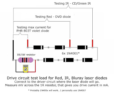
Dummy or test load would cost about $1 to make, with parts which you , most certanly, already have.

It is generally a bad idea to set the current while the diode is operational.
That's because the diode will light up and work properly at 50mA even, and you will never know if your diode is at optimal power at 100mA , or maybe you can push it a bit further? Driven with this question, you will ramp up the diode's current until you kill it.

The driver you've mentioned does not require all 6 rectifier diodes, it's a linear regulator so even only one single 1 ohm resistor will work.
Readon mV across 1ohm resistor will translate into mA across the load, according to Ohms Law.

If nothing else, you can try measuring the current directly from the output of the driver with mA settings on your Multimeter.

Oh, and Welcome to the forum :beer:
 
Joined
Jul 3, 2010
Messages
210
Points
0
Oh, I didnt know that the test load was only 1 dollar. I have only looked for some dummys at some larger websites, such as rkcstr, and at Stonetek, but have not found a cheap kit. I can probably get it now, mainly because of its low price <5$ =). With a bit more research I found out I needed six 14N001 rectifier diodes, a 1 ohm resistor, and a multimeter. What else do I need?
 
Joined
Jun 12, 2010
Messages
341
Points
0
its not gonna be blue btw lol. but if you hadnt noticed, theres great things happening in 445nm atm if you were considering it, 50$ diodes that can be run at 1W and all that.
 
Joined
Jul 3, 2010
Messages
210
Points
0
Yeah I know 405nm is a BIT purple, but hey.
Also for the 1 ohm resistor, can the wattage be lower than 1 watt? Will the lower wattage break the laser?
 
Joined
Jun 12, 2010
Messages
341
Points
0
it is pure purple, not just a bit
6xbrbeamlightsoff.jpg

im no expert, but P=I^2R
R will be 1
so, assuming you are running beneath 1 amp it should be fine AFAIK

hey that guy has my mouse lol
 
Last edited:
Joined
Jul 3, 2010
Messages
210
Points
0
I see now. It IS quite purple. Well, I only thought it was blue because it would "Fluorescence" off of some shades of white. But yes, I probably will start my 445nm laser project next year. I dont have enough money. So my test-load shall probably roll like this:
(Pathway)

9v battery,
Battery Lead,
Laser Diode Driver
Driver output leads
1N4001,
1N4001,
1N4001,
1N4001,
1N4001,
1N4001,
and then the 1 ohm 1/2 watt resistor.

Will it be ok, so that none of my parts get damaged?
And also so that all of the parts work together nicely?

By the way, if thats like the mouse you have, it looks like a Razer!
I have a Razer Salmosa.
 
Joined
Jun 12, 2010
Messages
341
Points
0
mines a razer copperhead

test+load02.jpg


half a watt should be ok if you're only using ~200mA or less
remember the multimeter in parallel
 
Joined
Jul 3, 2010
Messages
210
Points
0
One last question, I have bought a few rectifier diodes (1N4001), from a nearby RadioShack. I am wondering if ALL 1N4001 have the same stats, because the specs on them looked a bit weird.

That is all, thanks for your help.
 
Joined
Feb 5, 2008
Messages
6,252
Points
83
One last question, I have bought a few rectifier diodes (1N4001), from a nearby RadioShack. I am wondering if ALL 1N4001 have the same stats, because the specs on them looked a bit weird.

That is all, thanks for your help.
All 1n400x diodes have about the same Vdrop , which is what we want, so yeah - they are all fine. Difference between 4001 through 4007 is how much voltage they can take,
IIRC 4001 can take up to 50V, and 4007 can take 1kV.
 
Joined
Apr 28, 2009
Messages
2,416
Points
63
Just don't forget to short the output of the driver circuit with power off, and then solder your laser diode wires to the power supply. Otherwise you are guaranteed to destroy your laser diode.
 
Joined
Feb 5, 2008
Messages
6,252
Points
83
Just don't forget to short the output of the driver circuit with power off, and then solder your laser diode wires to the power supply. Otherwise you are guaranteed to destroy your laser diode.
Only if the driver has been powered without load at some point before connecting laser diode. Otherwise, no discharge needed - if you first unpowered the driver, then disconnected load and then soldered the diode, no need to worry.
 
Joined
Jul 3, 2010
Messages
210
Points
0
I am a bit confused with the last two posts by Eudaimonium and millirad.

All I am doing is just soldering on the leads from my power supply to the imputs of the driver, then soldering on the diode onto the driver outputs.

Just don't forget to short the output of the driver circuit with power off, and then solder your laser diode wires to the power supply. Otherwise you are guaranteed to destroy your laser diode.

^ But then why would it destroy the diode?
 
Joined
Jun 12, 2010
Messages
341
Points
0
its just incase of residual charges. and remember to connect the switch inbetween the battery and the driver.
 
Joined
Apr 28, 2009
Messages
2,416
Points
63
If you have a filter capacitor, and the suppy is powered up, you must short out the filter cap before soldering on the laser diode. The capacitor will dump a spike of voltage across the Laser Diode, instantly killing it.


Top