

- Joined
- Mar 27, 2011
- Messages
- 506
- Points
- 63
This is not a sale thread!
This is a discussion thread.
For a sale thread, please go to >here<
Hello all!
BACKGROUND STORY
So long story short, at first i kinda hesitant to design and manufacture a driver because i think people already satisfied with currently available driver,
But since i saw that there are so many monster diode emerged from the depth of a hell, and not to mention the declining stock of driver in market,
Then i decided to design a 12A buck driver with the dimension is only 15*10mm.
And due to addiction in designing things, i continue another one with boost topology capable of delivering 9A current with only 12.5*10mm.
After that, i think that i need to provide one to be used with low power diode,
So i design another one, a small one for small laser diode.
In the middle of design times i scaled down both the 12A and 9A to 6A, because i think it's not quite useful for now.
So the final are 6A for both buck and boost driver.
DRIVERS AND SPECIFICATION
ASTRAL SUPERDRIVE HV (STATUS: INACTIVE - WAITING FOR PRODUCTION)
Retail price: $19.9
ASTRAL SUPERDRIVE LV (STATUS: INACTIVE - WAITING FOR PRODUCTION)
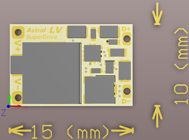
Retail price: $24.9
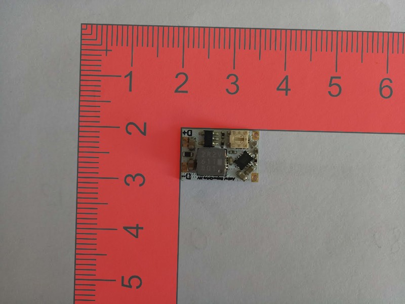
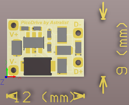
ASTRAL PICODRIVE (STATUS: ACTIVE - IN PRODUCTION)
Retail price: $14.9
ASTRAL EZ DRIVE (STATUS: INACTIVE - WAITING FOR PRODUCTION)
Retail price: $14.9
All of the driver above can be modded to be able to accept TTL/PWM, Except the EZDrive
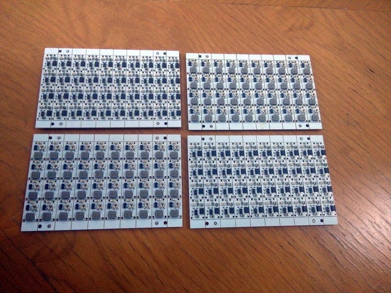
The driver is completed
I only fabricate in small number for now
I hope these can balance the supply and demand of driver these day
Thanks for looking! :beer:
This is a discussion thread.
For a sale thread, please go to >here<
Hello all!
BACKGROUND STORY
So long story short, at first i kinda hesitant to design and manufacture a driver because i think people already satisfied with currently available driver,
But since i saw that there are so many monster diode emerged from the depth of a hell, and not to mention the declining stock of driver in market,
Then i decided to design a 12A buck driver with the dimension is only 15*10mm.
And due to addiction in designing things, i continue another one with boost topology capable of delivering 9A current with only 12.5*10mm.
After that, i think that i need to provide one to be used with low power diode,
So i design another one, a small one for small laser diode.
In the middle of design times i scaled down both the 12A and 9A to 6A, because i think it's not quite useful for now.
So the final are 6A for both buck and boost driver.
DRIVERS AND SPECIFICATION
ASTRAL SUPERDRIVE HV (STATUS: INACTIVE - WAITING FOR PRODUCTION)
Retail price: $19.9
- Topology: Buck (When operating, Vin must be above Vout/diode Vf)
- Vin: 4.5 - 18V
- Vout: 0.7 - 8V
- Iout: 1.1 - 6A
- Size: 15*10mm
- Features:
- Current regulated
- Adjustable current
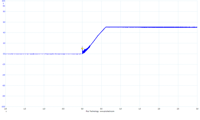
- Soft start (1sec)
- Delayed start (1.5sec+)
- Thermal shutdown
- PCB with 2oz (70um) copper, twice the copper thickness of usual PCB to maximize current and heat transfer.
- Components mounted only on top side of PCB, allowing maximum contact from driver to heatsink, hence maximizing heat transfer from PCB to heatsink.
- Thin PCB with lots of vias, maximizing heat transfer from top side to bottom side.
- Component mounted and soldered using automated assembly machine, minimizing human error.
- Continuous ground/negative
ASTRAL SUPERDRIVE LV (STATUS: INACTIVE - WAITING FOR PRODUCTION)
Retail price: $24.9
- Topology: Boost (When operating, Vin must be below Vout/diode Vf)
- Vin: 1.9 - 4.2V
- Vout: 2.5 - 5.5V
- Iout: 1.2 - 4.5A+
- Size: 15*10mm
- Features:
- Current regulated
- Adjustable current
- Soft start (internal 3ms)
- Thermal shutdown
- PCB with 2oz (70um) copper, twice the copper thickness of usual PCB to maximize current and heat transfer.
- Components mounted only on top side of PCB, allowing maximum contact from driver to heatsink, hence maximizing heat transfer from PCB to heatsink.
- Thin PCB with lots of vias, maximizing heat transfer from top side to bottom side.
- Component mounted and soldered using automated assembly machine, minimizing human error.
- Continuous ground/negative
ASTRAL PICODRIVE (STATUS: ACTIVE - IN PRODUCTION)
Retail price: $14.9
- Topology: Boost (When operating, Vin must be below Vout/diode Vf)
- Vin: 2 - 24V
- Vout: 2.5 - 28V
- Iout: 70 - 1500mA+ (depends on Vout)
- Size: 12*9mm
- Features:
- Current regulated
- Adjustable current
- Soft start (internal)
- Thermal shutdown
- Thin PCB with lots of vias, maximizing heat transfer from top side to bottom side.
- Component mounted and soldered using automated assembly machine, minimizing human error.
- Continuous ground/negative
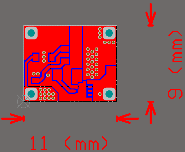
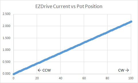
ASTRAL EZ DRIVE (STATUS: INACTIVE - WAITING FOR PRODUCTION)
Retail price: $14.9
- Topology: Linear (When operating, Vin must be above Vout/diode Vf)
- Vin: 3 - 12V
- Vout: (Vin - 1.5)V
- Iout: 0 - 2200mA
- Size: 11*9mm
- Features:
- Current regulated
- Adjustable current
- Components mounted only on top side of PCB, allowing maximum contact from driver to heatsink, hence maximizing heat transfer from PCB to heatsink.
- Very thin PCB with lots of vias, maximizing heat transfer from top side to bottom side.
- Component mounted and soldered using automated assembly machine, minimizing human error.
- Continuous positive
All of the driver above can be modded to be able to accept TTL/PWM, Except the EZDrive
The driver is completed
I only fabricate in small number for now
I hope these can balance the supply and demand of driver these day
Thanks for looking! :beer:
Last edited:


