Welcome to Laser Pointer Forums - discuss green laser pointers, blue laser pointers, and all types of lasers

LPF Donation via Stripe | LPF Donation - Other Methods

Links below open in new window

ArcticMyst Security by Avery

Adding an LED to your driver? :thinking:

Joined
Mar 21, 2011
Messages
368
Points
28
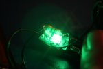
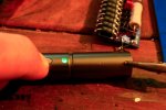
I'm working on a 445 build and I want to incorporate an LED into the build so that when the laser is powered on the LED also lights up. I'm using one of the ghostdrives at 501 mA. The setup is pictured below. Any ideas? PS: I had a few drinks while I was soldering this up so be kind...;)
attachment.php

attachment.php

attachment.php
 

Attachments

  • 1.jpg
    1.jpg
    73.5 KB · Views: 511
  • 2.jpg
    2.jpg
    85.1 KB · Views: 519
  • 3.jpg
    3.jpg
    53.9 KB · Views: 516


Joined
Dec 11, 2011
Messages
4,364
Points
83
Easily done.

Simply take the desired LED and current limiting resistor for the LED and put them in parallel with the driver's Power IN leads.

IMPORTANT: The LED and LED Resistor are in series with each other. The LED and Resistor go in parallel with the driver.

So it would be:

Driver in +
|
Z
Z (resistor)
Z
|
|
V LED
|
|
Driver in -
 
Last edited:
Joined
Mar 21, 2011
Messages
368
Points
28
Thanks! Ill post here with the results when I get time to put it together, now the question is which color LED best suits a 445....
 
Joined
Jan 29, 2012
Messages
3,164
Points
113
Hmm depends if you want to see the LED when wearing your goggles and the lasers on! ;)
 

Hiemal

0
Joined
Dec 27, 2011
Messages
1,443
Points
63
In that case, go with red or yellow! :D

With standard LED's the usual current is around 20 mA. Since you're presumably using 2 li-ions for this setup, that would equate to around 8.4 volts fully charged.

Based off of that, R = 8.4 / 0.02

R = 420 ohms.

Hope that helps!
 
Joined
Mar 21, 2011
Messages
368
Points
28
Ok, so I bought some green and blue 2.0 mm diffused LEDs and I think I'm gonna go with the green. Thanks for the resistor calculation Le Quack ;)
 

Dam

0
Joined
Jun 21, 2009
Messages
58
Points
8
I think 20mA will be too much for 2mm LED. Even 1k resistor will guarantee you that you will find this LED too bright and annoying. You can use even 2-5k resistor for dimmer output. If you wire the LED+resistor parallel with laser diode driver OUTPUT, there will be kind of "laser-on indicator LED". When will the LED+resistor be placed parallel to the battery at the laser diode driver INPUT there will be LED lighted whenever you insert the battery and it will be "power indicator LED".

This will be best setup:

LASER DIODE
+....................... _

|.........................|
|.........................|
|.........................|
---LED--resistor---
|.........................|
|.........................|
DRIVER OUTPUT
 
Last edited:

Benm

0
Joined
Aug 16, 2007
Messages
7,896
Points
113
I'd disagree with the above: If you put the led on the output, it will share the current with the laser diode, resulting in lower laser output. This may not be much, but from an electronics perspective its still the 'wrong' thing to do.

You should put the led on the input of the driver as suggested, and -after- the power switch, so that it only lights up when you switch the laser on.

As for the color of the led, i'd go for red or yellow... green will be blocked by many goggles as they are oftend intended for use with both 532 and 445 lasers.
 
Joined
Mar 29, 2011
Messages
1,056
Points
48
I'd disagree with the above: If you put the led on the output, it will share the current with the laser diode, resulting in lower laser output. This may not be much, but from an electronics perspective its still the 'wrong' thing to do.

You should put the led on the input of the driver as suggested, and -after- the power switch, so that it only lights up when you switch the laser on.

As for the color of the led, i'd go for red or yellow... green will be blocked by many goggles as they are oftend intended for use with both 532 and 445 lasers.

^ absolutely correct, put the led on the input instead of output.

And I think a white led would be nice too :)
 
Joined
Dec 11, 2011
Messages
4,364
Points
83
Ditto with Benm and Foul;

Most DIY builds don't have a switch on the driver, so there is no current at the driver input when the laser diode is off.
 
Joined
Mar 21, 2011
Messages
368
Points
28
Thanks Sigurthr and everyone else for your input. I still have to shrink wrap the connections but it's alive!!! ;)
attachment.php

attachment.php

attachment.php
 

Attachments

  • 5.jpg
    5.jpg
    70.4 KB · Views: 413
  • 6.jpg
    6.jpg
    33 KB · Views: 369
  • 7.jpg
    7.jpg
    66.4 KB · Views: 419
Last edited:
Joined
May 12, 2013
Messages
751
Points
43
Rather than creating a new thread I thought I'd ask a relevant question here :)

I am looking to build a laser with essentially the same design elements as the one above and would like to have an led indicator which is always on when the batteries are in regardless of whether or not the laser is powered on. This will provide an added safety mechanism since it provides the user with a visual indication of loaded batteries and would ensure that the user takes the batteries out once finished.

As I understand, this would require placing the led and resistor in parallel with the positive and negative inputs of the switch rather than the driver. Would this pose any detrimental effect on the components of the laser? I'll be using an x-drive v6 along with the supplied momentary switch that came with the leadlight.
 
Last edited:
Joined
May 14, 2013
Messages
3,438
Points
0
Rather than creating a new thread I though I'd ask a relevant question here :)

I am looking to build a laser with essentially the same design elements as the one above and would like to have an led indicator which is always on when the batteries are in regardless of whether or not the laser is powered on. This will provide an added safety mechanism since it provides the user with a visual indication of loaded batteries and would ensure that the user takes the batteries out once finished.

As I understand this would require putting the led and resistor in parallel with the positive and negative inputs of the switch rather than the driver. Would this pose any detrimental effect on the components of the laser? I'll be using an x-drive v6 along with the supplied momentary switch that came with the leadlight.

Always on when the batteries or battery is in won't work well in parallel with the switch, it would work but you are in effect partly closing the switch as soon as you put the batteries in, meaning that the switch is partly on, it really needs to be in parallel with the batteries. The switch should be between the batteries and the driver. This will have no effect on any components of the laser except to have a small drain on the batteries.

Alan
 
Joined
May 12, 2013
Messages
751
Points
43
Thanks Pi R,

Regarding the slight drain on the batteries that's kinda the point :beer:

In effect it will remind the end user to remove the batteries once operation has finished. With these kind of obscenely powerful leadlights that can turn on extremely easily it is imperative that they do not remain 'loaded' when not in use.

However I don't understand why this won't work well, what exactly do you mean by 'partly closing the switch'? Also, isn't in parallel with the batteries kinda the same thing as in parallel with the switch? since the led and resistor are placed in parallel with the switches input there is no current going through the switch before it is depressed, thus the switch won't be 'partly on', which is physically impossible I'm pretty sure. I dunno, am I missing something? :undecided:


Top