

Jufran88
0
- Joined
- Feb 9, 2011
- Messages
- 578
- Points
- 0
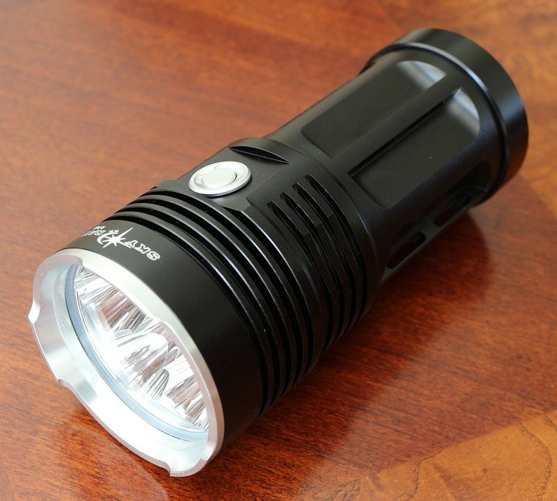
Hey guys, here is a quick tear down of the 6 x XM-L2 SRK clone I received from DX a few weeks ago. It's an overall great light and is easily moddable to get increased output.
From what I noticed all the PCBs have no finish, its all copper. No HASL or ENIG. The light comes with lubricated threads which is a plus!
Mods I did:

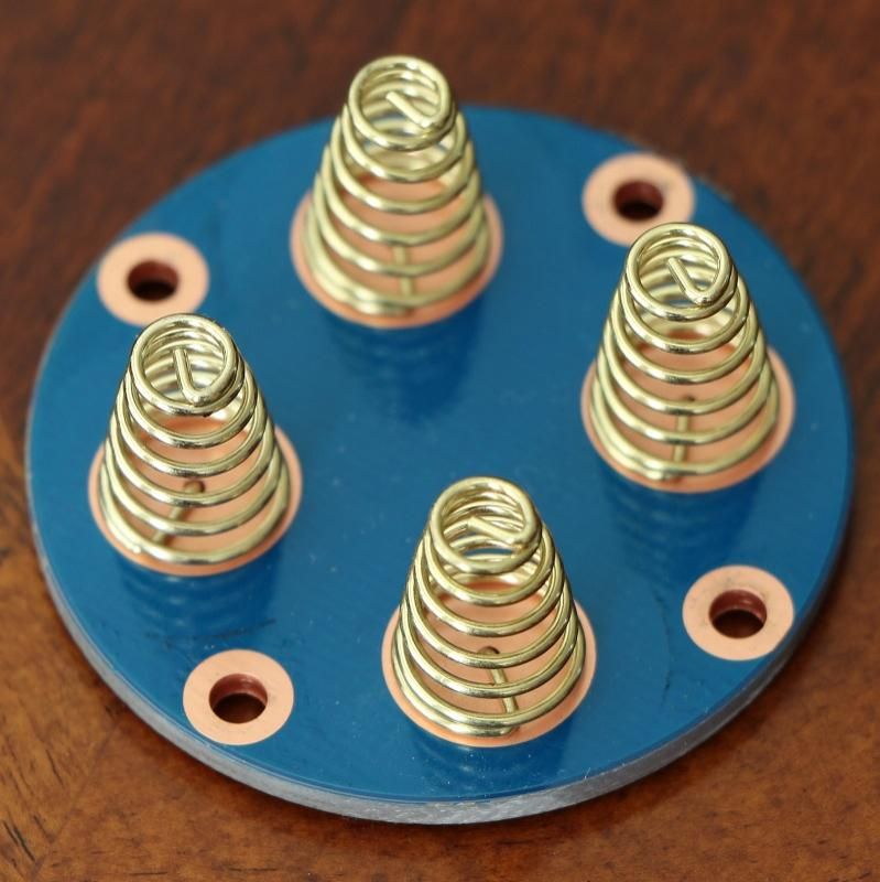
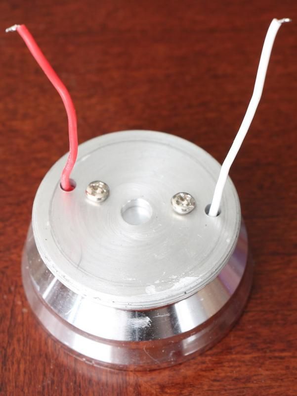
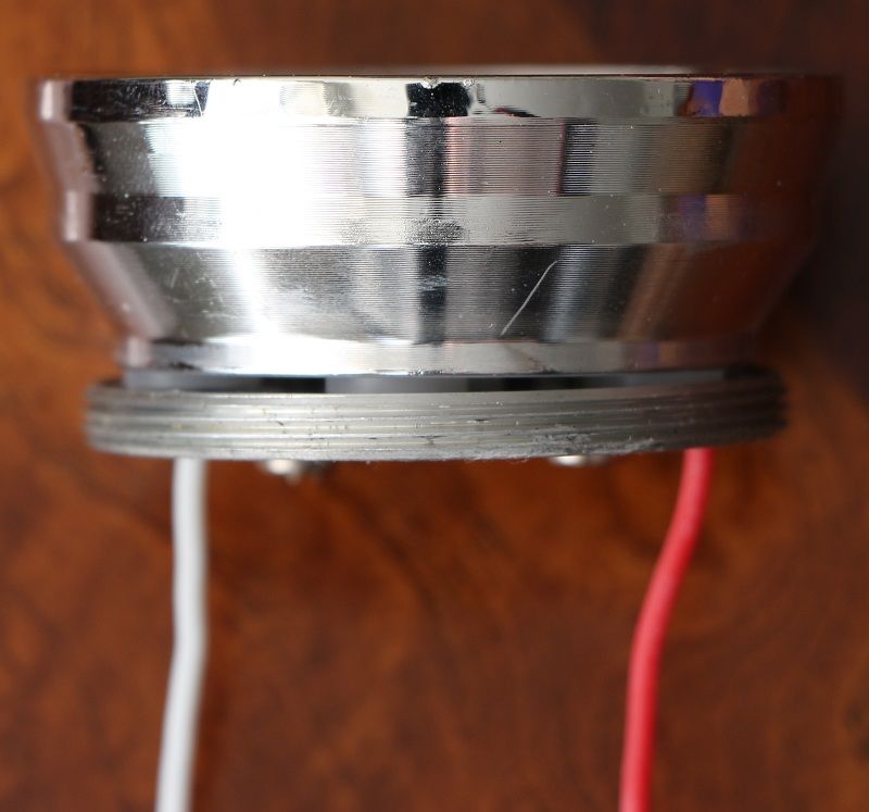
Unscrewing the bottom will reveal the screwed in battery contact plate. Copper springs are soldered on the back rather than the front.
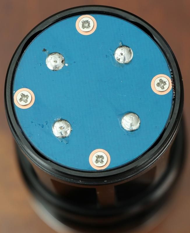
The copper pads around the screws make contact with the body allowing the negative feed to the driver.
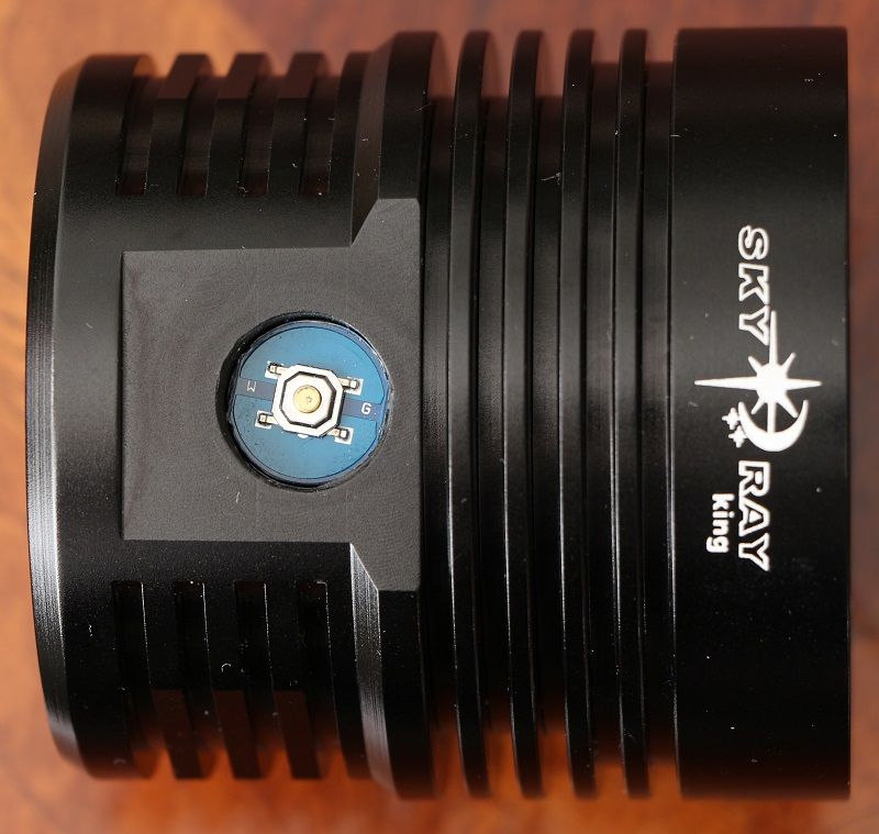
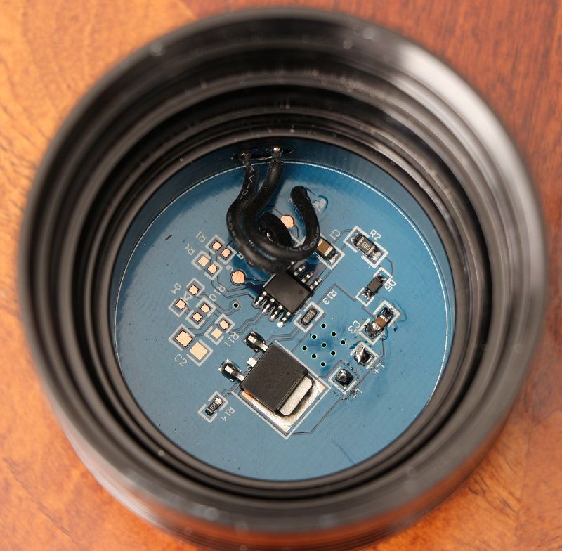
Electronic switch
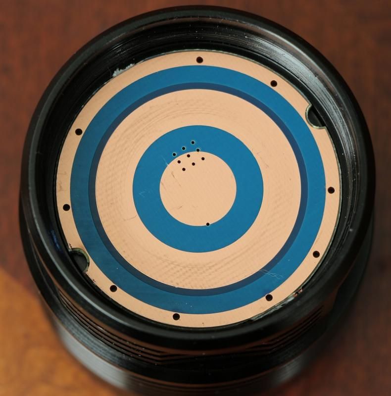
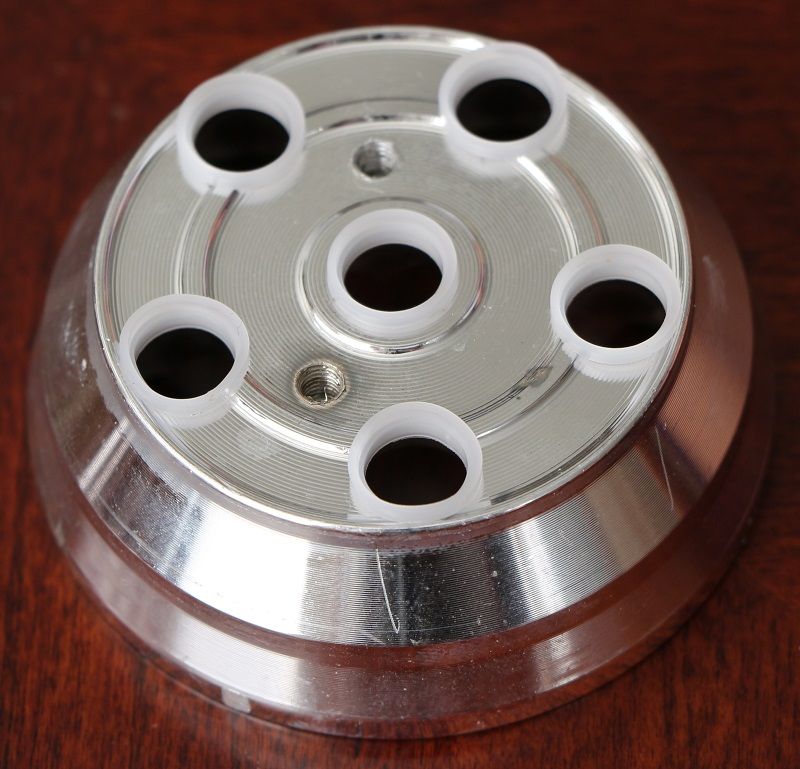
Inner and middle ring are positive contacts while the outermost ring is the negative contact. Driver is not glued in!!! It's pressed in.
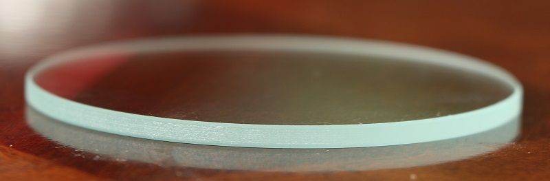
Glass lens: 54.8mm x 2.4mm
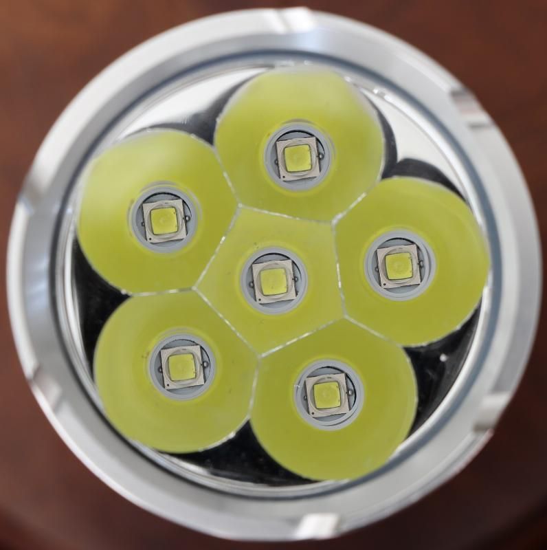
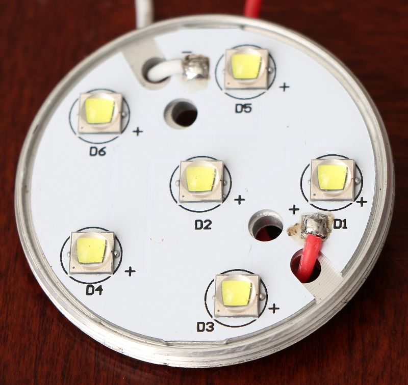
Unscrewing the reflector and desoldering the LED wires will get you here. The reflector might be tightly screwed in so a bit of force may be needed.
Take off the reflector screws and underneath you will the insulation gaskets. They just pop right in there. It's a bit high so cutting them down might increase output by a tiny bit.
LEDs are in parallel
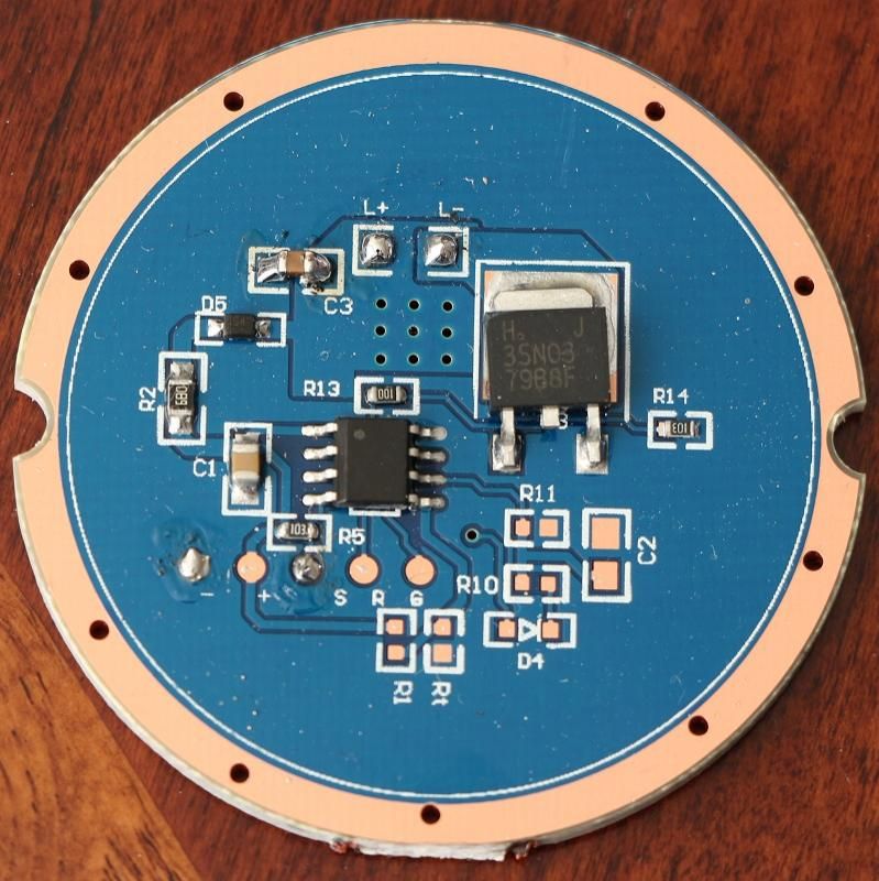
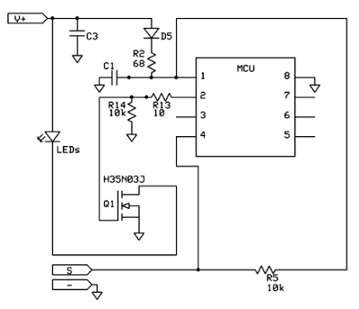
Driver: 46.5mm MOSFET driven H35N03J
Driver schematic with all components used and unused
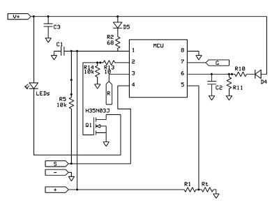
Driver schematic with only populated components
Again this is a great light with a lot of potential! After modding it I noticed a huge increase in light output. It would be a lot brighter if I had some high drain batteries.
Thanks for looking! :beer:
From what I noticed all the PCBs have no finish, its all copper. No HASL or ENIG. The light comes with lubricated threads which is a plus!
Mods I did:
- Changed wiring to 18 gauge silicone wire
- MOSFET swap
- Re-pasted star to pill using Shin-Etsu thermal paste
- Cleaned all contact points with 91% alcohol and Deoxit
Unscrewing the bottom will reveal the screwed in battery contact plate. Copper springs are soldered on the back rather than the front.
The copper pads around the screws make contact with the body allowing the negative feed to the driver.
Electronic switch
Inner and middle ring are positive contacts while the outermost ring is the negative contact. Driver is not glued in!!! It's pressed in.
Glass lens: 54.8mm x 2.4mm
Unscrewing the reflector and desoldering the LED wires will get you here. The reflector might be tightly screwed in so a bit of force may be needed.
Take off the reflector screws and underneath you will the insulation gaskets. They just pop right in there. It's a bit high so cutting them down might increase output by a tiny bit.
LEDs are in parallel
Driver: 46.5mm MOSFET driven H35N03J
Driver schematic with all components used and unused
Driver schematic with only populated components
Again this is a great light with a lot of potential! After modding it I noticed a huge increase in light output. It would be a lot brighter if I had some high drain batteries.
Thanks for looking! :beer:


