Welcome to Laser Pointer Forums - discuss green laser pointers, blue laser pointers, and all types of lasers

LPF Donation via Stripe | LPF Donation - Other Methods

Links below open in new window

ArcticMyst Security by Avery

445 build help

Joined
Sep 19, 2010
Messages
702
Points
0
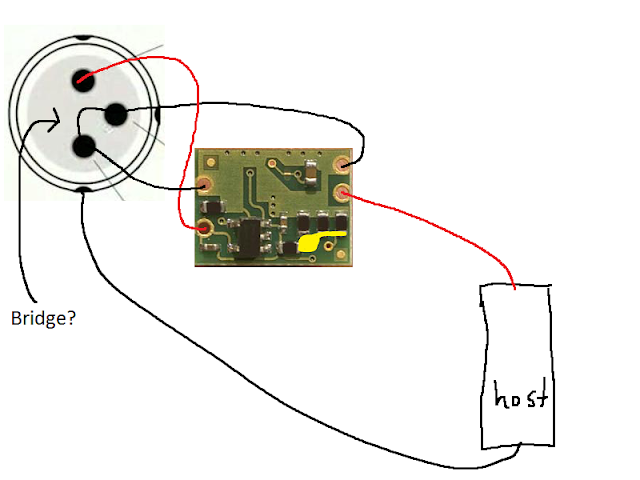
So i am working on a 445 build with a v5, set up my flexdrive, sinked it attached +battery on the flex to the host's +. Then i got my flaminpyro tested a140 out and attached it to the flexdrive (I have my driver set up so the -battery goes to the case pin of the diode.) I popped in a battery to make sure it was all good, but got no light. Tried a new battery and still no luck. So i took out my next diode and soldered it on and again no light. So i took the driver back out hooked it up to my DMM and i get the same 1.1A reading as i initially set it up as. I am completely lost on this.

Any ideas?


daguin

0
Joined
Mar 29, 2008
Messages
15,989
Points
113
Can you draw a schematic of how you have it wired up?

Peace,
dave
 
Joined
Sep 19, 2010
Messages
702
Points
0
auyu61.png


best i could do
 
Joined
Aug 13, 2010
Messages
839
Points
28
You still need to ground the diode to the host if you want this to work
Make sure the anodizing isn't interrupting the circuit.
Aluminum anodizing is by design very electrically insulative.
A wrap of electrical tape is a good plan to make sure the driver isn't shorting to the host as well ;)
 
Last edited:
Joined
Sep 19, 2010
Messages
702
Points
0
Ground the diode to the host... How do I go about doing that... I just did it all the same way as my ehgemus host... Is that different because it is a direct press?
 
Joined
May 25, 2010
Messages
3,655
Points
0
Ground the diode to the host... How do I go about doing that... I just did it all the same way as my ehgemus host... Is that different because it is a direct press?

No, You got it Right. He was Just pointing out that it should be grounded to bare metal like the Aixiz Module touching the heatsink and then touching the inside walls of the host. If the Inside host walls were anodized then you would not have a good connection if you even get one.

Is your host anodized.?:)
 

mmykle

0
Joined
Dec 4, 2007
Messages
194
Points
0
Why is the middle pin connected to the battery negative port? Isn't the 445 a case neutral like the blurays? It's been a long time since I've done a build (and I don't have a 445 yet), but is that the correct way to wire a 445?
 
Joined
Sep 19, 2010
Messages
702
Points
0
Why is the middle pin connected to the battery negative port? Isn't the 445 a case neutral like the blurays? It's been a long time since I've done a build (and I don't have a 445 yet), but is that the correct way to wire a 445?

You can do it this way or bridge the case and negative pins of the diode and have no wire coming from the batt -
 

mmykle

0
Joined
Dec 4, 2007
Messages
194
Points
0
You can do it this way or bridge the case and negative pins of the diode and have no wire coming from the batt -

So like this, I don't really get what that bridge would do?

I don't get how the wiring mark posted would work either, but with your suggestion I can see how the negative battery terminal connects with the negative terminal on the driver.

wiring.png
 

daguin

0
Joined
Mar 29, 2008
Messages
15,989
Points
113
So like this, I don't really get what that bridge would do?

I don't get how the wiring mark posted would work either, but with your suggestion I can see how the negative battery terminal connects with the negative terminal on the driver.

wiring.png
With a MICROFLEX (using the case as the negative path), you can wire it either way because the negative path on the driver is continuous in the driver.

With the MICROBOOST you must use the case pin to negative driver input wire technique to use the case as the negative path. The negative path in the microboost is NOT continuous. If you bridge the case pin to the negative pin, when using the case as the negative path, you effectively bypass the driver (giving the diode a direct connection to the battery).

@ the OP -- Check to make sure that you have good electrical connection at all contact points. The possibility of an anodized contact point may be it. Also, you may have a short or a break somewhere that only manifests itself when it is assembled. Finally, make sure that you are placing the battery in the correct direction and that it is actually making contact at both ends.

Peace,
dave
 
Last edited:
Joined
Sep 19, 2010
Messages
702
Points
0
@ the OP -- Check to make sure that you have good electrical connection at all contact points. The possibility of an anodized contact point may be it. Also, you may have a short or a break somewhere that only manifests itself when it is assembled. Finally, make sure that you are placing the battery in the correct direction and that it is actually making contact at both ends.

Peace,
dave

Maybe I should also test to make sure the diodes work? I can't imagine all three were DOA, but i rather just see it to make sure.

Can i just attach the battery to the driver inputs and the outputs of the driver to the diode and just leave the case pin untouched to test it?

2j11q9w.png
 
Last edited:
Joined
May 4, 2009
Messages
5,443
Points
113
I know the diode I sent you works just fine I tested it just befor I packaged it and sent it to you.

Peace All...


Maybe I should also test to make sure the diodes work? I can't imagine all three were DOA, but i rather just see it to make sure.
 
Joined
Sep 19, 2010
Messages
702
Points
0
I know the diode I sent you works just fine I tested it just befor I packaged it and sent it to you.

Peace All...

Yea, i was just wondering if somehow it could died in transit, im not sure how often that happens. Im really just grasping for anything at this point :crackup:. I'm sure it is just something small that i am doing wrong, but its hard to figure out the problem with not much experience.
 

daguin

0
Joined
Mar 29, 2008
Messages
15,989
Points
113
Maybe I should also test to make sure the diodes work? I can't imagine all three were DOA, but i rather just see it to make sure.

Can i just attach the battery to the driver inputs and the outputs of the driver to the diode and just leave the case pin untouched to test it?

2j11q9w.png

If you hook it up just like this, you will know if it is working. Do not run it for a very long time without a good heat sink on it

And be careful which way it is pointing ;)

Peace,
dave
 

mmykle

0
Joined
Dec 4, 2007
Messages
194
Points
0
Thanks Dagiun! I've got the microflex V3 (I know it's old, but it will work so whatever) so I get how to do it.

I don't understand what you mean by using the pin-bridge method with the microboost. It sounds like you're contridicting your statement, saying that you should use the pin-bridge method if using a case-negative build but that in doing so you'll bypass the driver. So you should just never use the pin-bridge method with the microboost? :thinking:

With a MICROFLEX (using the case as the negative path), you can wire it either way because the negative path on the driver is continuous in the driver.

With the MICROBOOST you must use the case pin to negative driver input wire technique to use the case as the negative path. The negative path in the microboost is NOT continuous. If you bridge the case pin to the negative pin, when using the case as the negative path, you effectively bypass the driver (giving the diode a direct connection to the battery).

@ the OP -- Check to make sure that you have good electrical connection at all contact points. The possibility of an anodized contact point may be it. Also, you may have a short or a break somewhere that only manifests itself when it is assembled. Finally, make sure that you are placing the battery in the correct direction and that it is actually making contact at both ends.

Peace,
dave
 

daguin

0
Joined
Mar 29, 2008
Messages
15,989
Points
113
Thanks Dagiun! I've got the microflex V3 (I know it's old, but it will work so whatever) so I get how to do it.

I don't understand what you mean by using the pin-bridge method with the microboost. It sounds like you're contridicting your statement, saying that you should use the pin-bridge method if using a case-negative build but that in doing so you'll bypass the driver. So you should just never use the pin-bridge method with the microboost? :thinking:

Sorry for not being clear.

Correct. You should not use the pin-bridge method with the microboost.

Either leave it floating completely, (if you can have both leads to the input and output side of the driver),
OR

Use the case pin to driver INPUT as shown above (if you are using the case as the negative path).

With the microflex, you can use the pin-bridge method (if you are using the case as the negative path) without the pin to input wire.

Peace,
dave


Top