Welcome to Laser Pointer Forums - discuss green laser pointers, blue laser pointers, and all types of lasers

LPF Donation via Stripe | LPF Donation - Other Methods

Links below open in new window

ArcticMyst Security by Avery

2 diodes, both dim? (Now w/ Pics)

Joined
Jan 13, 2008
Messages
16
Points
0
First, I created the driver on a breadboard and hooked everything up. The laser was bright as hell! I couldn't even look at it around 200mW. So, then I soldered everything to the cb hooked it all up, turned it on and it was pretty dimm. I mean using the pot still changed it but it looked like a 2mW laser pointer at it's brightest. I thought I killed it somehow so I re-soldered another laser diode to the circuit. Again the same crap.?!?!? I only got one diode left, and I don't want to mess it up. Please someone help me out here.
Oh, While I had it powered on I measured the mA and it was around 200.


Also, I am using 4 N type batteries 1.5v * 4 = 6V


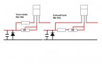
How do you properly discharge the cap?
Thanks


Joined
Jan 13, 2008
Messages
16
Points
0
Re: 2 diodes, both dim?

Well, I tried hooking up the last one I had. I checked for voltage at the cap and there was like 1.5v, so I shorted a wire to both leads? I touched across both leads, checked for voltage and nothing. Checked for mA and nothing. I reattached the diode hooked everything back up and still it's dim? wtf? I don't get it.
 
Joined
Oct 28, 2007
Messages
2,631
Points
48
Re: 2 diodes, both dim?

boost_dependent said:
Well, I tried hooking up the last one I had.  I checked for voltage at the cap and there was like 1.5v, so I shorted a wire to both leads?  I touched across both leads, checked for voltage and nothing.  Checked for mA and nothing.  I reattached the diode hooked everything back up and still it's dim?  wtf?  I don't get it.

wither ur getting the diode too hot, or theres a problem with ur cicuit. post pics so we can see if anything is shorting

oh and can you see a focused dot on a wall 4 ft away? how bout 12 ft away?
 
Joined
Jan 13, 2008
Messages
16
Points
0
Re: 2 diodes, both dim?

the forum won't let me post links.....?!?!?


Man, I got about 8 good pics of my setup but the forum won't let me post them?
 
Joined
Oct 28, 2007
Messages
2,631
Points
48
Re: 2 diodes, both dim?

u need 10 posts to p[ost links

jsut do it like:

h ttp://whatever.com

put a space between h and ttp

also, do your N cell batteries provide enough mAh?

try it with 6 AA batts.

then again it worked on ur bradboard....
 
Joined
Jul 24, 2007
Messages
2,749
Points
0
Re: 2 diodes, both dim?

When you rebuilt the circuit, did you test it before adding the LD?
It is easy to get something wrong between breadboard and end product.

Always check a new circuit before adding the LD. 4 Diodes cost cents your LD's cost $.

@boost..... I know It "may" be too late for your LD's but I want to get across to anyone else who is new to the hobby, who may read this thread, that a few minutes of simple testing saves a lot of expense and heartache.

Fingers crossed that you have just wired something wrongly and all is not lost.

Regards rog8811
 
Joined
Jan 13, 2008
Messages
16
Points
0
Re: 2 diodes, both dim?

This is on the breadboard, and it worked great! Very bright dot!!
h ttp://farm3.static.flickr.com/2189/2188116155_d99a23a503_b.jpg
FULL SIZE: h ttp://farm3.static.flickr.com/2189/2188116155_ff0f932227_o.jpg

--------

All these had really really dim dots
h ttp://farm3.static.flickr.com/2287/2188902594_3f75150d40_b.jpg
Full Size: h ttp://farm3.static.flickr.com/2287/2188902594_55281c2442_o.jpg

h ttp://farm3.static.flickr.com/2119/2188902398_105dde9594_b.jpg
Full Size: h ttp://farm3.static.flickr.com/2119/2188902398_0b6c65af00_o.jpg

h ttp://farm3.static.flickr.com/2139/2188902050_7050e90347_b.jpg
Full Size: h ttp://farm3.static.flickr.com/2139/2188902050_29f3378ef3_o.jpg

h ttp://farm3.static.flickr.com/2245/2188901866_e49b89f9a9_b.jpg
Full Size: h ttp://farm3.static.flickr.com/2245/2188901866_9106b330a4_o.jpg

h ttp://farm3.static.flickr.com/2102/2188114993_ce8b0d5fa7_b.jpg
Full Size: h ttp://farm3.static.flickr.com/2102/2188114993_54df583249_o.jpg

h ttp://farm3.static.flickr.com/2285/2188114653_59e9502213_b.jpg
Full Size: h ttp://farm3.static.flickr.com/2285/2188114653_9d414f6b18_o.jpg

Hope those help :)
 
Joined
Oct 28, 2007
Messages
2,631
Points
48
Joined
Nov 9, 2007
Messages
1,045
Points
0
did you short out the capacitor before you connected both of the diodes?

...lazer... ;D ;D ;D
 
Joined
Oct 28, 2007
Messages
2,631
Points
48
wooooooolazer said:
did you short out the capacitor before you connected both of the diodes?

...lazer... ;D ;D ;D

didnt he say he did?

and we need dot pics, that way we can tell you for SURE if your diode is dead or not.
 
Joined
Nov 9, 2007
Messages
1,045
Points
0
For the second one he did but i dont think he did for the first, that is probably why the first one died. When you tried to measure the ma going to it did you happen to put the meter in paralel with the circuit and measure ma with that, if you did that then that will kill the diode... the current needs to be measured by putting the meter in series with a 1ohm resistor then setting it to milivolts and whatever milivolts it shows will be the current.

...lazer.... ;D ;D ;D
 
Joined
Jul 24, 2007
Messages
2,749
Points
0
Just check where your output to the diode/capacitor/LD positive is coming from.

It is a bit difficult to see from the pictues but it looks to me as if you have taken the output from between the parallel resistors and the variable resistor. I may be wrong but check it.

Regards rog8811
 

Attachments

  • Driver_fault01.jpg
    Driver_fault01.jpg
    45.3 KB · Views: 95
Joined
Jan 13, 2008
Messages
16
Points
0
here are the pics of the dot. Sorry I couldn't hold the beam exactly steady on some of them.

This is about 4ft away with the pot turned to full resistance.
h ttp://farm3.static.flickr.com/2106/2190862918_4c01f837a8_o.jpg


4ft away pot turned down all the way
h ttp://farm3.static.flickr.com/2306/2190862966_e9c2cd3520_o.jpg


About 12ft away or so, pot turned to max resistance
h ttp://farm3.static.flickr.com/2065/2190075749_57386b8d2d_o.jpg


About 12ft away pot at least resistance.
h ttp://farm3.static.flickr.com/2233/2190075837_a657993bf5_o.jpg

These pics are cropped, so if you need to see the full uncropped photo let me know.
 
Joined
Jan 13, 2008
Messages
16
Points
0
rog8811 said:
Just check where your output to the diode/capacitor/LD positive is coming from.

It is a bit difficult to see from the pictues but it looks to me as if you have taken the output from between the parallel resistors and the variable resistor. I may be wrong but check it.

Regards rog8811


so, what would the outcome be of the 2 variations you just listed?
 
Joined
Jul 24, 2007
Messages
2,749
Points
0
First is wrong, second is right ;)


It would muck up the regulation, no sure exactly how but could make the LD dim

Regards rog8811

**Edit, I have had a bit of a think about it, you stand the chance of having no resistance between the reg and the LD, have you measured the ref voltage between the heatsink and adj (pin1)? If it isn't 1.25v there is a problem.........
 
Joined
Jan 13, 2008
Messages
16
Points
0
rog8811 said:
First is wrong, second is right ;)


It would muck up the regulation, no sure exactly how but could make the LD dim

Regards rog8811

**Edit, I have had a bit of a think about it, you stand the chance of having no resistance between the reg and the LD, have you measured the ref voltage between the heatsink and adj (pin1)? If it isn't 1.25v there is a problem.........


I haven't changed the resistors to the correct way yet. I'm not sure how you want me to get the ref voltage. I tried going from the heatsink to the adj pin and it didn't read anything. The only way I can read V there is to go from ground to one of the 3 pins. Power had 5.95v, vout had 5.55, and adj had 5.55v


Top