Hello people , i got dvd rw laser and built laser driver , laser works and shines very bright but doesnt burn anything , its from lg dvd , power supply 12v 5 amo driver . Im using my own build bosy for laser , from dvd lens . Anyone can help?
LPF Donation via Stripe | LPF Donation - Other Methods
Links below open in new window
ArcticMyst Security by Avery


You are using an out of date browser. It may not display this or other websites correctly.
You should upgrade or use an alternative browser.
You should upgrade or use an alternative browser.
Dvd Rw red laser
- Thread starter Mikash
- Start date


Immo1282
0
- Joined
- Sep 4, 2018
- Messages
- 562
- Points
- 63
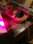
In order to burn with this kind of diode you need to hit the object you want to burn with the exact focused spot instead of the big spread out blob you can see here. I'd take a look with some smoke to find out where the spot is and try with that.
But for god's sake - get some safety glasses! It's not worth losing your eyesight over trying to burn some things close up.
But for god's sake - get some safety glasses! It's not worth losing your eyesight over trying to burn some things close up.
thank you for your answer , it seems on picture that this laser point spot is big ) but it isnot ) i think maybe its problem with my build ? If ill take laser of that body must it burn something witjout lens ? Or please tell me what to do)In order to burn with this kind of diode you need to hit the object you want to burn with the exact focused spot instead of the big spread out blob you can see here. I'd take a look with some smoke to find out where the spot is and try with that.
But for god's sake - get some safety glasses! It's not worth losing your eyesight over trying to burn some things close up.
Immo1282
0
- Joined
- Sep 4, 2018
- Messages
- 562
- Points
- 63
Firstly - this forum is a hugely useful bank of historical information - Take a search using the box up ^there^ to try and find some answers.
Secondly - would be good of you to read the stickied threads and post an introduction in the Welcome section - it's far easier for people to help if we know a little bit about you and what you're trying to do.
No laser diode will burn anything without a lens in front of it. Most diodes have a high divergence which is correctable but only using a lens in front of them.
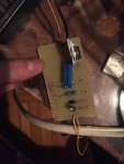
That day i leded my laser , killed ) today i got new lasersfrom dvd but until i connected them to my created driver i tested out voltage on driver and it shows 12 volt on out pins , it is connected on dc 12 v 5a . Seems like i killed lm317? How much must be viltage on out pins ? Thank you . I used lm317, 2x 10ohm resistor , 100ohm potentiometer , in4007 diode , 50v 10uf cap. What have i done wrong ? Here is from what photo i created driver .
Attachments
Immo1282
0
- Joined
- Sep 4, 2018
- Messages
- 562
- Points
- 63
LM317's are extremely robust devices - but that "schematic" is a total joke - let's be real here it's not a proper schematic, it's useless as polarised components are not labeled (output cap and LM317). Look for a proper schematic of a current-regulator using the LM317 and compare to see if your circuit is even remotely functional.That day i leded my laser , killed ) today i got new lasersfrom dvd but until i connected them to my created driver i tested out voltage on driver and it shows 12 volt on out pins , it is connected on dc 12 v 5a . Seems like i killed lm317? How much must be viltage on out pins ? Thank you . I used lm317, 2x 10ohm resistor , 100ohm potentiometer , in4007 diode , 50v 10uf cap. What have i done wrong ? Here is from what photo i created driver .
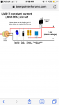
This should be a current regulated driver. The output voltage (that you feed the diode) is not important and will vary depending on the load, as the driver attempts to output a constant current. You should test your driver with a circuit like the image I have included, which will set the voltage depending on the number of diodes in series. The current in the test-load circuit can be measured as the voltage across the 1 ohm shunt resistor. You can scale up the current rating of the diodes you use and the shunt resistor as needed.

With no load (Test-load or laser diode unconnected), the output voltage of that regulator will be as close to the input as the circuit can, as the regulator desperately tries to compensate for the zero current.
Before you kill another diode - build yourself a test load and make sure your driver is regulating the output current, instead of the output voltage.
Immo1282
0
- Joined
- Sep 4, 2018
- Messages
- 562
- Points
- 63
Standard high (ish) current silicon rectifier diodes. I used 400V 3A diodes I think.What diodes can i use to build this test load circuit ?
Last edited:
Anthony P
Well-known member
- Joined
- Oct 7, 2018
- Messages
- 529
- Points
- 63
I use 1n4001 for <1amp. 1n5401 good up to 3amp. As IMMO said, use the test load. There are many on this site that know far more than me, but I really doubt a dvd diode requires that much current... probably why it died.
diachi
0
- Joined
- Feb 22, 2008
- Messages
- 9,700
- Points
- 113
As others have said, you need a test load. You must set the driver's current to something appropriate using the test load before attaching the laser diode. If you have no load attached the output will just go to the highest possible voltage (limited by your input voltage and the dropout of the regulator) as it tries to reach the current limit.
Make sure to discharge the output if you've run it without a load, as the output capacitors will be sitting at 12V and will kill a laser diode if you connect it.
Make sure to discharge the output if you've run it without a load, as the output capacitors will be sitting at 12V and will kill a laser diode if you connect it.
I built test load with 10 1n4002 diodes but i cannot measure current , dont understand why, i think its my viltmeters foult .its very cheap one , when i set it in DCA and then on 10 A mode shows nothing and on 200m mode shows 0.02. Dont know ehat to di(
Immo1282
0
- Joined
- Sep 4, 2018
- Messages
- 562
- Points
- 63
You don't measure the current in the test load. Measure the voltage across the 1 Ohm resistor. V=IR, so by measuring the voltage across a known resistance you can calculate the current flowing in it. For a 1Ohm resistor this is easy as 1V=1A.I built test load with 10 1n4002 diodes but i cannot measure current , dont understand why, i think its my viltmeters foult .its very cheap one , when i set it in DCA and then on 10 A mode shows nothing and on 200m mode shows 0.02. Dont know ehat to di(
Short one of the jumpers (maybe the first or second from the left in that schematic) to attempt to get close to the operating voltage of the diode.
diachi
0
- Joined
- Feb 22, 2008
- Messages
- 9,700
- Points
- 113
I built test load with 10 1n4002 diodes but i cannot measure current , dont understand why, i think its my viltmeters foult .its very cheap one , when i set it in DCA and then on 10 A mode shows nothing and on 200m mode shows 0.02. Dont know ehat to di(
You're using too many diodes, the voltage drop across the test diodes should be equal (or close to) the voltage drop across the laser diode. 4 diodes is all you need for a red laser diode.
diachi
0
- Joined
- Feb 22, 2008
- Messages
- 9,700
- Points
- 113
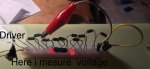
Here is what i did
I thought the positive and negative rails on those breadboards consisted of one contact? In which case that's basically just a big short circuit with a 1ohm resistor thrown in.
Correct me if I'm wrong?
