Welcome to Laser Pointer Forums - discuss green laser pointers, blue laser pointers, and all types of lasers

LPF Donation via Stripe | LPF Donation - Other Methods

Links below open in new window

ArcticMyst Security by Avery

Got my arduino uno today and a open USB to Serial (arduino)

Joined
Jul 4, 2008
Messages
2,499
Points
113
Well today was fairly successful. I scored a new shop in Seoul, Yongsan Electronics mall that carries just about everything one needs for building their own LPM and or Portable laser.
Details will be up on the stickies for those members in S.Korea.

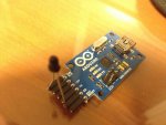
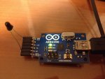
Anyways. I am converting an old Hioki 3803 that has a RS232C optical connection to a Arduino digital TX signal. I disconnected the IR diode and soldiered two jumpers, one to LED + and the other to ground.
The Positive jumper was added to TX and the ground went to ground on the
USB2SERIAL.

Here is the data that came off the Hioki at 9600baud.


ÒÖ"‡òRåëÒÖ"‡òRåëÒÖ*>>
åëÒÖ*>>
åëgòòv>>
åëgòòv>>
åëòÒ6²v>>
åëòÒ6²v>>
åëÒÖÖ"‡òRåëÒÖÖ"‡òRåë³röòrŸay�³röòrŸay³röòrŸay�³röòrŸay³röòrŸay�³röòrŸay³röòrŸay�³röòrŸay³röòrŸay�³röòrŸay³röòrŸay�³röòrŸay³röòrŸay�³röòrŸayÒ¶¶ör>>
åëÒ¶¶ör>>
åëòòòòrŸay�òòòòrŸayòòòòrŸay�òòòòrŸayòòòòrŸay�òòòòrŸayòòòòrŸay�òòòòrŸayòòòòrŸay�òòòòrŸayòòòòrŸay�òòòòrŸayòòòòrŸay�òòòòrŸaygòòòr>>
åëgòòòr>>
åëÒv6vŸay�Òv6vŸayÒVRRrŸay�ÒVRRrŸay³röòrŸay�³röòrŸay³röòrŸay�³röòrŸay³röòrŸay�³röòrŸay³röòrŸay�³röòrŸay³röòrŸay�³röòrŸay³röòrŸay�³röòrŸay³röòrŸay�³röòr>>
åëg³ÙYÉÈìRåëg³ÙYÉÈìRåëg&Rò‡ìRåëg&Rò‡ìRåëg&gRrŸay�–ÒöRrŸay³röòrŸay�³röòrŸay³röòrŸay�³röòrŸay³röòrŸay�³röòrŸay³röòrŸay�³röòrŸaygÒ¶¶vŸay�öÒ¶¶vŸaygòrvv>>
åëgòrvv>>
åëgòòÒŸay�öòòÒŸaygòRÒvŸay�öòRÒvŸaygòòòrŸay�öòòòrŸayòòòòrŸay�òòòòrŸayòòòòrŸay�òòòòrŸayòòòòrŸay�òòòòrŸayòòòòrŸay�òòòòrŸayòòòòrŸay�òòòòrŸayòòòòrŸay�òòòòrŸayü

röòrŸay�³ should read 4.0Vdc

I am trying to research how to decipher this raw data out. What to do... .

The idea is to put the SERIAL2USB into the hioki to bypass the RS232C and go directly to digital out.
 
Last edited:


Things

0
Joined
May 1, 2007
Messages
7,517
Points
0
Hmm, how about trying a different baud rate? If you still can't get sensible data, then it's probably encoded somehow and will be a pain to reverse engineer.
 
Joined
Jul 4, 2008
Messages
2,499
Points
113
Hmm, how about trying a different baud rate? If you still can't get sensible data, then it's probably encoded somehow and will be a pain to reverse engineer.

hmm, did that... Seems to be some sort of IR code.
9600 is the correct baud setting.

:beer:

Anyone who has an idea, feel free to let me know.
I ran out of time today on this.
Tomorrow afternoon I'm going to figure it out.
 
Joined
Jul 27, 2007
Messages
3,642
Points
63
It is unlikely that the IR communication is direct RS232, but if it is you will need to invert the signal since RS232 is active low and TTL (on the arduino) is active high.
 
Joined
Jul 4, 2008
Messages
2,499
Points
113
It is unlikely that the IR communication is direct RS232, but if it is you will need to invert the signal since RS232 is active low and TTL (on the arduino) is active high.

You hit the nail on the head.
I tried both ways to create a data flow through the RX on the USB2SERIAL.
the pulses are too strong from the meter and reset the connection. I have to manually reset the USB2SERIAL.
Anyways.. I tried the tutorial from 2 sites. I was correct about the data flow only occurring at 9600baud. That is what the Hioki uses as a connection.
Unlocking RS232 serial comm on a multimeter

Also this one shows how to build the adapter using the USB2SERIAL.
AMB Laboratories DIY Audio ? View topic - DIY: hacking multimeters for RS232 data logging output.

Following the last tutorial, I used the arduino program to monitor the data flow. What I got was hexadecimal code. Useful code.

Just as this was working.. I noticed my meter indicating a low battery.
:rolleyes: :undecided:.... less than 6.7V... time for a new battery.

So the optical connection works fine, so long as you can decode the
hexadecimal. 1251FFE05078048
using a serial monitor program with a Hex decoder.
Fortunately there such a program for DMMs called QtDmm. It workes for Linux, MacOSX and windows.

I think these tutorials could work well for making data out connections for
DIY LPMs.
Ideally one should look at a microcontroller such as an Arduino or better, this way you could program the output into something that is a little more "universal" / easier to work with.
Converting an older DMM that uses serial is a pain in the butt... Also every DMM will have a different baud setting and coding....

Hopefully some of you out there might find this info useful.
 
Last edited:
Joined
Jul 4, 2008
Messages
2,499
Points
113
Well, here are some pictures showing the adapter I made to decode IR signals from the meter.
I had quite a bit of fun with this today.
It sees just about every kind of IR signal, either from remote controls, cell phone screen (off/on) proximity sensors and RX data from a Opto isolated
DMM such as a Hioki DMM..

When a pulsed IR source is put up directly to the IR pin diode (right in front of the diode window), the TX data
strobes orange indicating a connection. In the Arduino program on serial monitor, the USB2SERIAL writes data onto the screen.
If all is going correctly you should see HEX code appearing. 12234FF003A... etc.
Adjust the baud rate accordingly. Chances are that most meters start at 9600baud and go from there up.

--- Now that I see it works with other meters, my DMM is transmitting an idle code 1 pulse per second. This is a bad sign as this means that the DMMs transmission part of the processor dosen't work at all. I tried this adapter on another meter and it fed back Hex that was readable on qtdmm and CoolTerminal. :undecided:
1 problem down another to go. grr....
 

Attachments

  • IMG_1163.JPG
    IMG_1163.JPG
    132.6 KB · Views: 422
  • IMG_1164.JPG
    IMG_1164.JPG
    133.1 KB · Views: 3,029
Last edited:
Joined
Jul 27, 2007
Messages
3,642
Points
63
I'm surprised you're getting anything at all just by hooking the phototransistor directly to the input of the converter module - you really should use a proper buffering circuit.
 
Joined
Jul 4, 2008
Messages
2,499
Points
113
I'm surprised you're getting anything at all just by hooking the phototransistor directly to the input of the converter module - you really should use a proper buffering circuit.

The Arduino board has been used in the manner I've been using on several tutorials.
What kind of buffer are you recommending.
Arduino - USBSerial

I followed the other tutorials and though one had a buffer it used a different USB2SERIAL board, the others using this Arduino do not use such a buffer. hmm... :confused:

Actually a little update. There is a similar project here using a 3 pin (IR photo transistor and an Arduino uno) It too doesn't use a "buffer" but rather the
digital inputs and a +3.3v pin.
http://learn.adafruit.com/ir-sensor/making-an-intervalometer
I have now decoded my Sony remote using my adapter on 9600baud. It works.
 

Attachments

  • USB_serial04-LIGTH-sch.pdf
    54.6 KB · Views: 158
Last edited:


Top