lazeerer
0
- Joined
- May 25, 2010
- Messages
- 3,655
- Points
- 0
Hi All,
Well about a week ago i realized when trying to set a driver to a higher amperage the dummy / test load Keeped on getting super hot really quickly. The test load got so hot After about 5 second that i had to take breaks after that 5 seconds were up for about 1 to 2 minutes to let the test load cool down.
Well even by doing this i ended up burning up the SMD 1 ohm resistor that comes stock on my test load. So i purchased another one to replace it with. After this i still was have trouble with it getting to hot really quickly.
So what i decided to do was heatsink the Test Load and let me tell you it has solved all the problems.:wave: I heatsink the 6 diodes as well as the resistor that i got to replace the original SMD one. Iam waiting for a new one to come in the mail because before i heatsinked the test load and resistor i was using the new resistor with out it being heatsink that is why you see slight burn marks on the resistor. But it has not effected the test and is still reading 1 ohms. Once the new 1 ohm resistor comes in iam going to replace the slightly burnt color one in the video with the new one that is coming in.
So if you set alot of drivers over 1amp 1.5amp or 1.9amps etc or even just for personal DIY laser builds definitely give this a go. It does not effect the acutely output of the test. I made sure to check if the output was the same before and after heatsinking.
Check out this video i did to show you all how long it can be left on Running at 1770mA/1.77amps with no problem of over heating or smoking anything.:beer: I could have left it on longer but i dint want to bore you Guy's. :na:
Closer Pictures of the heatsinking it self. The smaller heatsink is detachable form the larger heatsinking by a screw to make it more portable like:
The new resistor should be in this week to replace the one you see in the picture. This was caused before heatsink the 6 diodes and resistor. You can also see i left enough room to be able to change between Re and Blu Mode.


So If you want to do this mod Here are a little tips:
You Will Need:
Thermal Adhesive. It must be adhesive or it wont stick.
Link:
Amazon.com: Arctic Alumina Thermal Adhesive (Two Tube Set): Electronics
A vice or something that can hold the heatsink to the 6 diodes when the thermal adhesive is setting. "You can use your hands but depending on what adhesive you buy you could be holding it for a wail. The one i used from a friend sets in 5 minutes."
Your DIY Test Load or the Rkcstr version like i have."If you are using the Rkcstr one like i have you will need a through hole resistor as well as if your DIY test load is SMD you will also need a through hole resistor."
You can get a 1 ohm resistor at Digikey.com or any other place you like.
1)You will need to mix up the adhesive if it is a 2 part mix 50% A + 50% B.
2) Then apply enough to cover the 6 diodes.
3) After applying the thermal adhesive you will need to place the heatsink on top of the 6 diodes where you applied the thermal adhesive and then put it into a vice to set for about 10 min i would call safe if you re using the thermal adhesive that i used in the link above. If you are not using the same as the link above please fallow the direction on the back of your thermal adhesive and allow that amount of time for it to set."Note: if you are using the Rkcstr test/dummy load please take a look to where you place the heatsink and make sure you leave enough room to switch in between the Red and Blu setting on the test load."
4) Once that has set it is now time for you to mix up some more thermal adhesive to mount the resistor to the heatsink. The way i did is before soldering the resistor to the test load i formed it into the correct shape then i soldered it in place and took the thermal adhesive and applied it under the resistor with a tooth pic. Your DIY test load will be a different set up so just form the resistor to best fit your design of the test load.
5) Your Done.
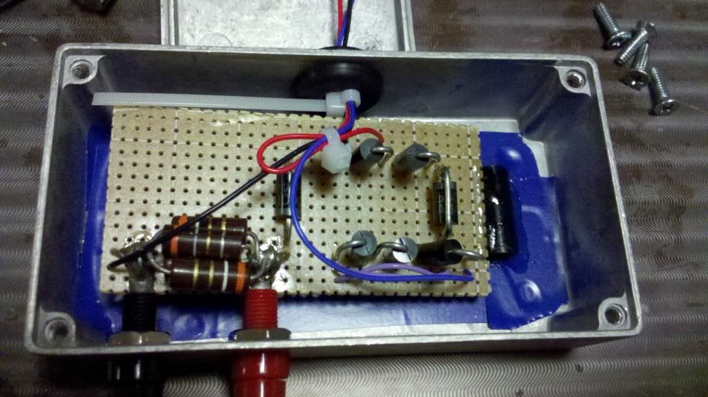
Another tip i can say is if you have the Rkcstr test load you can look at the pictures above to see that i added 2 long strips of metal that i took from an old resistor and soldered them to the test load where you would hook up your DMM to. Makes things easier to use alligator clips then to try and use prongs to hold them in place and set the current.
Also i ran a black and red wire from the test load that would connect to my driver to make it also more easier to hook up when you re ready to set your current.
I hope this helps.
:thanks: For Looking .!!!
Well about a week ago i realized when trying to set a driver to a higher amperage the dummy / test load Keeped on getting super hot really quickly. The test load got so hot After about 5 second that i had to take breaks after that 5 seconds were up for about 1 to 2 minutes to let the test load cool down.
Well even by doing this i ended up burning up the SMD 1 ohm resistor that comes stock on my test load. So i purchased another one to replace it with. After this i still was have trouble with it getting to hot really quickly.
So what i decided to do was heatsink the Test Load and let me tell you it has solved all the problems.:wave: I heatsink the 6 diodes as well as the resistor that i got to replace the original SMD one. Iam waiting for a new one to come in the mail because before i heatsinked the test load and resistor i was using the new resistor with out it being heatsink that is why you see slight burn marks on the resistor. But it has not effected the test and is still reading 1 ohms. Once the new 1 ohm resistor comes in iam going to replace the slightly burnt color one in the video with the new one that is coming in.
So if you set alot of drivers over 1amp 1.5amp or 1.9amps etc or even just for personal DIY laser builds definitely give this a go. It does not effect the acutely output of the test. I made sure to check if the output was the same before and after heatsinking.
Check out this video i did to show you all how long it can be left on Running at 1770mA/1.77amps with no problem of over heating or smoking anything.:beer: I could have left it on longer but i dint want to bore you Guy's. :na:
Closer Pictures of the heatsinking it self. The smaller heatsink is detachable form the larger heatsinking by a screw to make it more portable like:
The new resistor should be in this week to replace the one you see in the picture. This was caused before heatsink the 6 diodes and resistor. You can also see i left enough room to be able to change between Re and Blu Mode.
So If you want to do this mod Here are a little tips:
You Will Need:
Thermal Adhesive. It must be adhesive or it wont stick.
Link:
Amazon.com: Arctic Alumina Thermal Adhesive (Two Tube Set): Electronics
A vice or something that can hold the heatsink to the 6 diodes when the thermal adhesive is setting. "You can use your hands but depending on what adhesive you buy you could be holding it for a wail. The one i used from a friend sets in 5 minutes."
Your DIY Test Load or the Rkcstr version like i have."If you are using the Rkcstr one like i have you will need a through hole resistor as well as if your DIY test load is SMD you will also need a through hole resistor."
You can get a 1 ohm resistor at Digikey.com or any other place you like.
1)You will need to mix up the adhesive if it is a 2 part mix 50% A + 50% B.
2) Then apply enough to cover the 6 diodes.
3) After applying the thermal adhesive you will need to place the heatsink on top of the 6 diodes where you applied the thermal adhesive and then put it into a vice to set for about 10 min i would call safe if you re using the thermal adhesive that i used in the link above. If you are not using the same as the link above please fallow the direction on the back of your thermal adhesive and allow that amount of time for it to set."Note: if you are using the Rkcstr test/dummy load please take a look to where you place the heatsink and make sure you leave enough room to switch in between the Red and Blu setting on the test load."
4) Once that has set it is now time for you to mix up some more thermal adhesive to mount the resistor to the heatsink. The way i did is before soldering the resistor to the test load i formed it into the correct shape then i soldered it in place and took the thermal adhesive and applied it under the resistor with a tooth pic. Your DIY test load will be a different set up so just form the resistor to best fit your design of the test load.
5) Your Done.
Another tip i can say is if you have the Rkcstr test load you can look at the pictures above to see that i added 2 long strips of metal that i took from an old resistor and soldered them to the test load where you would hook up your DMM to. Makes things easier to use alligator clips then to try and use prongs to hold them in place and set the current.
Also i ran a black and red wire from the test load that would connect to my driver to make it also more easier to hook up when you re ready to set your current.
I hope this helps.
:thanks: For Looking .!!!