ped
0
- Joined
- Nov 25, 2008
- Messages
- 4,889
- Points
- 113
Hi guys, to go with these new high power 635's that are available now, what are you using as a test load to set current? does anyone have a diagram?


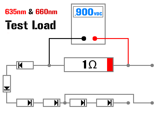
I just want to point out that the normal RED logic fails us with respect to test loads for the 635s.
At 1A, those 1N400X or 1N540X diodes start to drop closer to 1V each. If you're placing 4 of them in series, and also dropping ~1V across the resistor, than you're really talking about something between 4.5 and 5V of simulated Vf.
IIRC, these Mitsubishi reds only have a Vf of something like 3.5, when run at 1A (that's a rough memory though - confirm before taking my word for it)

