Welcome to Laser Pointer Forums - discuss green laser pointers, blue laser pointers, and all types of lasers

LPF Donation via Stripe | LPF Donation - Other Methods

Links below open in new window

ArcticMyst Security by Avery

Test load question?

Joined
Dec 27, 2011
Messages
2,062
Points
48
Instead of running a bunch of diodes in series to create a test load, why not just chose some zeners dialed in at red, blue and violet voltage drops?

Is it a practical matter? Is it too hard to find a 3v Zener that can handle 500mA? Or 4v Zener that can do 4A?

Or am I missing something bigger in the picture?

:thanks:


Joined
Sep 12, 2007
Messages
9,399
Points
113
Zener over series/parallel regular diodes: advantages:
smaller
simpler

disadvantages:
far more costly
can be difficult to find, especially in high powers
good for simulating only one voltage
 
Joined
Dec 27, 2011
Messages
2,062
Points
48
Zener over series/parallel regular diodes: advantages:
smaller
simpler

disadvantages:
far more costly
can be difficult to find, especially in high powers
good for simulating only one voltage

My thinking was to get two or three, design the PCB with jumpers or a switch that routes through matching Vf Zener for red, blue or violet.

Smaller size, and is per design as you said.

Ease of build is worth $ in some cases, rather than soldering 9 or 10 diodes.

I guess the answer I am looking for is that it CAN be done, just maybe more expensive and the main thing is finding the high wattage zeners.

I'll look into it, thank for the tips!

EDIT: found this...

The maximum current through a zener diode is determined by ...

I = P / V * where I = current, P = zener power rating, and V = zener voltage rating.
For example, a 27V 1W zener can carry a maximum continuous current of ...
I = 1 / 27 = 0.037A = 37mA

For optimum zener operation, it is best to keep the current to a maximum of 0.7 of the claimed maximum, so the 27V zener should not be run at more than about 26mA. This becomes the base current for the power transistor, and assuming a current gain of 25, that means the total 'composite zener' current is ...

26 x 25 = 650mA

The voltage is increased slightly (to about 27.7V), and the power rating is now ...
P = V * I * = 18W (minimum)

A darlington transistor can also be used for higher current, but will add around 1.5V to the zener voltage. Whether this will cause a problem or not depends on the circuit itself, and is not something that can be predicted in advance.

Construction

Construction is not critical, but a heatsink will almost certainly be needed for Q1. Using a clip to attach D1 to the heatsink will allow a higher dissipation, and will allow you to operate the zener at its maximum operating current. Select Q1 to suit the application - in many cases, a raid on the junk box will almost certainly provide something usable. R1 can be 0.25 or 0.5W.
 
Last edited:
Joined
Dec 29, 2009
Messages
3,136
Points
63
I think at some point, it becomes more economic to just buy another laser diode and use it as a test load... I mean, what better to simulate a component than another same component?
 
Joined
Dec 27, 2011
Messages
2,062
Points
48
I think at some point, it becomes more economic to just buy another laser diode and use it as a test load... I mean, what better to simulate a component than another same component?

Well, problem with that is...

If you are testing a high power driver you will need to have a very efficient diode to test with, and one really good diode for each color. And the whole time you will be thinking what a good pointer they would make.

Expensive! Easily $100+ in diodes alone.

Also if you screw up and dial in your violet diode when you are testing 1.9 watts then your diode is gone. If you choose 6v worth of diodes on a test load, no harm. Your red too.

You also have an annoying, bright, heat generating light when you test.

An LED that could handle the current might be good. Or a string, but I haven't researched it yet to see if there is an LED or string that would work.

EDIT: Here is a good LED site.

HB LED CATALOG

^^INTERESTING LED CATALOG^^
 
Last edited:

Hiemal

0
Joined
Dec 27, 2011
Messages
1,443
Points
63
A darlington transistor can also be used for higher current, but will add around 1.5V to the zener voltage. Whether this will cause a problem or not depends on the circuit itself, and is not something that can be predicted in advance.

Maybe this could be used to help.

Instead of using a huge zener diode why not use a small low wattage one, combined with the transistor?
 
Joined
Dec 27, 2011
Messages
2,062
Points
48
I = P / V * where I = current, P = zener power rating, and V = zener voltage rating.

So in this case, a 6V 5W zener can carry a maximum continuous current of ...

I = 5 / 6 = 830mA

Which isn't ideal. If I can get a 10W zener -that should work in most instances...

Reds = ~3v
Blues = ~4.5v (9mm up to 4.8v) - so maybe a 5v to cover blue safely?
Violet = ~6v


I = 10/6 = 1.66A and 6V would be plenty for violets.
I = 10/5 = 2.00A for blues
I = 10/3 = 3.33A for reds.

Actually, you could even refine your search to

6W/6V zener for violet (1.00A)
10W/5V for blue (2.00A)
and
5W/3V for reds (1.66A)

Now to find those zeners. (Please feel free to jump my case if I have a typo, brainfart or gross mistake on any of these calculations - I am in a less than ideal environment right now - kids, nieces, nephews and cousins running around the house).

EDIT: OK, this seems to go against my numbers...

1N3998 10W Zener diode 6,2V - 405mA- NEW - sealed

Not sure why that is only 405mA. If it was twice the current, that would be a good violet diode. Not TOO expensive except shipping is killing you.

OK, this PDF sheds more light.

1N3998 DATA SHEET

What is the ZENER TEST CURRENT? And what is the MAX DC CURRENT? Ok, I have found the answer to this question... and it is fairly good.

" There is a minimum zener current for which the stabilization of the voltage is effective and the zener current must stay above this value operating under load within its breakdown region at all times."

It looks like ZENER TEST CURRENT is probably ZENER CURRENT which is the minimum current for the zener to breakdown and flow. So maybe it needs a voltage AND a current to flow? Either way, it looks like that it is a LOW number, not a high limiting number. So having a 425mA zener current won't keep it from working. I THINK it is the MAX DC current we are working with. The downside is that it means the diode may not work because it won't run at low enough currents for some situations? Does that seem right? Any zener diode experts here?

So it seems like I can go forward in my post below outlining some possible zeners.
 
Last edited:
Joined
Sep 12, 2007
Messages
9,399
Points
113
rather than soldering 9 or 10 diodes.

Ah, yes. The common misconception that diodes always drop 0.7V. It's more like 0.8, 0.9, or 1V when driven at high current. People also forget to add the current sense resistor. They figure "4.2V for a blue. Divide that by 0.7... looks like I need 6 diodes." In fact this setup will drop closer to 7V. I don't see any case where you'd need 10 diodes. 5 will suffice for everything except direct injection green. That's only one more than the build you're proposing.
 
Joined
Dec 27, 2011
Messages
2,062
Points
48
Ok, this is starting to make me think the zener is not a good choice for a test load...

AN008 - How to Use Zener Diodes

"For optimum zener operation, it is best to keep the current to a maximum of 0.7 of the claimed maximum, so a 27V/2W zener should not be run at more than about 47mA. The ideal is probably about 25% of the maximum, as this minimizes wasted energy and ensures that the zener is operating within the most linear part of the curve.The test current is typically between 25% and 36% of the maximum continuous current. The wise reader will figure out that this range has been chosen to show the diode in the best possible light, and is therefore the recommended operating current .

Remember that a zener is much the same as a normal diode, except that it has a defined breakdown voltage that is far lower than any standard rectifier diode. Zeners are always connected with reverse polarity compared to a rectifier diode, so the cathode (the terminal with the band on the case) connects to the most positive point in the circuit.
"

This makes me think that the zener may have too narrow of a good operational range for a test load where you want the diode to behave the same way under a wide variety of currents.

If you are restricted to about 25%-70% of the rated current, that limits you pretty seriously on the blues.

For reds the zener will work well I think...

For violets you might find a good zener,

But for blues it would seem like another diode would be better suited. If someone has an idea that contradicts this, please let me know. As it stands now I think that I will stick with more traditional high power diodes for a test load. It would have been neat to find a three zener diode setup with a switch pointing to each choice, but I think it will be easier to find a nice, easily heat-sinked TO-220 or TO-247 diode that I can do 6 diodes (yes Cyparagon, I was aware that not all diodes drop .7v ;) ) and come up with a pretty flexible setup. I was just looking for a novel and elegant solution to the problem.
 
Last edited:

benmwv

0
Joined
Sep 10, 2010
Messages
1,380
Points
48
Sorry Tom but I think this is a bad idea. Using a Zener would give almost no flexibility. Simulating a 445 diode could take 3-5 standard diodes depending on current. The voltage over the diodes needs to be matched to the voltage over the resistor to equal approx the Vf of the simulated diode. Also when I test a driver I like to take it through various voltage levels to see what it can handle. You can't really do that using a Zener.

Using one Zener also means all the heat that would be spread across a few components is now in one.

I really don't think it's worth sacrificing so much just to avoid soldering 3 more diodes. It wouldn't even take 2 minutes.
 
Joined
Dec 27, 2011
Messages
2,062
Points
48
Sorry Tom but I think this is a bad idea. Using a Zener would give almost no flexibility. Simulating a 445 diode could take 3-5 standard diodes depending on current. The voltage over the diodes needs to be matched to the voltage over the resistor to equal approx the Vf of the simulated diode. Also when I test a driver I like to take it through various voltage levels to see what it can handle. You can't really do that using a Zener.

Using one Zener also means all the heat that would be spread across a few components is now in one.

I really don't think it's worth sacrificing so much just to avoid soldering 3 more diodes. It wouldn't even take 2 minutes.


Yeah, I was coming to that conclusion and typing it out when you responded... It was sort of an exercise in "what if?"

I'm going to go back to looking at various high-power diodes. I would like to use a high power diode that won't heat up so much to begin with, AND is easily heat sinked (like TO-220 or TO-247) and a resistor that is also very high power, low tolerance and easily sinked.
 

benmwv

0
Joined
Sep 10, 2010
Messages
1,380
Points
48
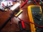
That's definitely the best way to do it. My test load is rock solid and the resistor doesn't even get warm. If I can find any pics of it here on my phone I'll show you what it looks like.

Here:
attachment.php

Excuse my messy desk :D
 

Attachments

  • IMG_0918.JPG
    IMG_0918.JPG
    157.2 KB · Views: 225
Last edited:
Joined
Sep 12, 2007
Messages
9,399
Points
113
You don't need to be worried about linearity in this application. The current sense resistor ruins it to start with, and laser diodes don't have it anyway. You also don't need to limit yourself to 70% rated current. You'll only be using it for a few minutes per year so over-driving it won't be a concern.


Top