Welcome to Laser Pointer Forums - discuss green laser pointers, blue laser pointers, and all types of lasers

LPF Donation via Stripe | LPF Donation - Other Methods

Links below open in new window

ArcticMyst Security by Avery

Problems with DIY driver?

Joined
Sep 22, 2010
Messages
1,358
Points
48
I have a quick question for you guys. I decided to build the DIY driver from Laser driver - It can be done as a way to get some experience. I built it according to the diagram and when I tested it after a slight tweaking of the pot it was putting out a steady 250mA. When I tested the output voltage it was at 5.1v which would fry my diode. Then I built my dummy load using the 4 diodes and followed by a 1ohm resister. When I measured across the resistor I was only getting .44v at 130mA which seems way wrong. I built it on a breadboard in case something like this happened and I need to rebuild it. Here's a picture of the driver plus test load. There is a jumper pin connecting the two pins on the pot like in the diagram that is hidden under the ground wire in the pic.

5052954027_e887c2d8b5.jpg


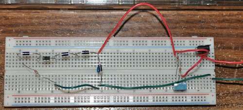
The full sized version can be found on my flickr page.
All sizes | driver | Flickr - Photo Sharing!

My power supply for the test was 4 fully charged eneloop AAs which were putting out about 5.3-5.4v total.


Joined
Oct 24, 2008
Messages
1,057
Points
48
What diode are you building this for? It looks like you set it up okay.

That set up is a current regulated driver. So depending on the load (diode) the LM317 will adjust the output voltage such that the current is what you set it at via the resistors. So you can't measure the output voltage (that 5.1v you measured) because that is subject to change.

Set up the driver again and measure the voltage across the 1 ohm resistor. That value does not reflect the output of the driver. The 4 diode eat up the rest of the voltage. Since the resistor is 1 ohm, 1mV across the resistor represents 1mA of current flowing through it. As you're measuring the voltage turn the pot and see if the voltage changes, it should. If you want 250mA then you'll want to set the pot until you measure .25v across the resistor.

-Tony
 

Rafa

0
Joined
Feb 4, 2010
Messages
437
Points
0
The problem is that you need at least 7.2V AKA 2 Li-Ion's
 
Joined
Oct 24, 2008
Messages
1,057
Points
48
Not if it is for a red or IR diode, which I am assuming he is going for seeing as hes only using 4 diodes to test his circuit.

-Tony
 
Joined
Sep 22, 2010
Messages
1,358
Points
48
You are correct it is a red diode. I completely forgot about the 1mW = 1mA across the resister even though I've read that in several places here. It didn't take long to get it tuned to 250mA. Unfortunately either the driver circuit still isn't working right, the diode was failing in the drive, or I managed to damage the diode (most likely) because when I hooked everything up I didn't get anything. I did a quick test using 2 AAs like has been posted in 1001 Youtube videos and barely had any output. In fact I couldn't see a dot until I held a piece of paper less than half an inch away. I think for my next attempt I may buy a couple prebuilt drivers and try to get in on styro's GB for some red diodes that I know aren't faulty if it's still going on payday next week.

I appreciate the help!

:thanks:
 
Joined
Aug 6, 2010
Messages
382
Points
0
Did you short the output leads to the diode to kill the residual in the capacitor before connecting the diode? You set the current so the capacitor was charged.
If not, you probably killed the diode. You won't even see a flicker when that happens.
Before connecting the diode....always short the diodes connections on the driver to kill the charge in the capacitor.
Been there and killed one like that. You don't walk alone.
 

Rafa

0
Joined
Feb 4, 2010
Messages
437
Points
0
Is the potentiometer in series? I can't see it in the picture.
 
Joined
Jul 30, 2010
Messages
215
Points
0
LtKernelPanic, I think you have your potentiometer connected as a constant resistor. If you connect the outer 2 legs you get the pot's full resistance all the time. You need to use the middle pin to get variable resistance. In the DDL schematic it's shown as 2 pins, middle and one side, connected to the current limiting resistors; the 3rd pin is connected to Vout. Check out this great article.

05149.png
 

Rafa

0
Joined
Feb 4, 2010
Messages
437
Points
0
LtKernelPanic, I think you have your potentiometer connected as a constant resistor. If you connect the outer 2 legs you get the pot's full resistance all the time. You need to use the middle pin to get variable resistance. In the DDL schematic it's shown as 2 pins, middle and one side, connected to the current limiting resistors; the 3rd pin is connected to Vout. Check out this great article.

05149.png
Thats what I mean.
 
Joined
Aug 6, 2010
Messages
382
Points
0
He says he had no trouble adjusting to 250ma. That would indicate the pot was working or he is on the right pins and had some adjustment. He has 2 10ohm diodes in parallel. 1 10ohm with no pot on a LM317 is 125ma. 2 in parallel is 5ohms and is 250ma. This tells me that the pot has to be a zero. But 250ma is to much for his diode. if that pot was 25ohm(guessing) the minimum he could have reached is abt 80ma. I cant tell for sure which lead the V+ is going to. If I go by the light color its in the middle. That cannot be and work. It should be in the far right and if he watched the vid it's clear in the one I saw. He says he has a jumper on the pot, cant see this, but if he jumped the wrong pins, he bypassed the pot and we are back to 250ma with a 5ohm resistor.

He never mentions not being able to adjust it. If he AA'd the diode as shown on YouTube it was dead at that point.

I'd suggest you get a couple of the cheap 5mw reds in a Sure module to test with. Better to kill a cheap one, it hurts less. @ 5mw you'll need 20-30ma so you'll have to remove one of the 10ohm resistors and then it should adjust down to 25-30ma if working correctly. Discharge the cap before connecting the diode too. I think I got my Sure from high Tech Dealz or ModWerx. $3.99?
 
Last edited:
Joined
Sep 22, 2010
Messages
1,358
Points
48
While not visible in the pic I posted there is a jumper pin that sits flush with the top of the breadboard (under the ground wire) connecting the left pin to the center pin as you look at the circuit. I honestly think my attempts at desoldering the stupid ribbon cable and soldering on leads probably killed it from the heat. The fact that I dropped it once too probably didn't help. The drive I harvested it from wouldn't finish burning a DVD either so maybe the diode was already going bad.

Like I said in my previous post I think I'm going to snag 5 of those reds (and maybe a BR or two) in styro's GB and a couple rckstr or lava drivers. If I get that working then I'll get a host and build a finished project.

Oh well live and learn. At lease I have my 1w 445 to play with for now. Just wish my glasses from OEM would get here so I can try the usual laser tricks with it.
 

Rafa

0
Joined
Feb 4, 2010
Messages
437
Points
0
Be careful with that 1W 445.
And yeah, you probably killed the diode. It can happen to anyone, man, don't worry. I have killed one LOC once, and several other diodes.
 
Joined
Aug 6, 2010
Messages
382
Points
0
LtKernelPanic, it would be easier to help if you answered the questions asked in the replies you received.
If you used a DVD burner that wasn't working correctly the diode may have been failing. It also might have been an IR diode. Invisible to the eye. All DVD burners do not have useable diodes from what I have read. CD/DVD burners especially fail unless it is a certain model sled. I still do more reading after 2 months than anything. As I read I order parts and have enough now to build at least 6 units. I've been doing a lot of bench testing and measurements. I've purchased a few pointers too.

As I read, I made a folder for Laser Data. I save every graph, detailed info into a file and good thread links in it. This gives me a quick reference when I am working on the bench till I can remember it all.
The YouTube vid with the AA test is horrible and should be deleted. A LD will draw everything it can, with no regulation, voltage and current into an instant death. No flash, flicker, nothing but a now dead diode.

Styros are a good buy and I have 6-7 of them. The more expensive sleds not only have the main diode you are wanting, but also one of the other 2 diodes can be a good low power red to use or test. So, 1 sled gives you 3 diodes, 2 useable ones, and one IR that most avoid, at least in the beginning with some optics to boot. A great deal IMO.

I would make a build check list to follow.
1. Connect the driver to test load.
2. Connect the supply power, check & set the driver output.
3. Unhook the test load, short the driver output leads to discharge the drivers capacitor.
4. Connect the diode which is pressed into a housing.

This is just my suggestion, but it works for me.
Good luck.
 
Joined
Sep 22, 2010
Messages
1,358
Points
48
Vaporizer- Somehow I missed your post. Been a crazy week at work. To answer your questions yes I did discharge the cap and tested it with my meter. It never read 0.00 but it never went over 0.01 either. The pot is a 100 ohm multiturn as recommended in the parts list on the page I linked to.

I also like your idea of keeping a folder for diagrams, pictures, and notes in. I'm going to start one to go along with the laser specific bookmarks folder I'd already have.

Now for an update. I think it was Bill Engvall who famously said "I'm an idiot" in one of his recent comedy specials. I was reading a couple threads last night to get a better idea of what to do/not to do on my next build when I read a post that said "an IR diode will appear as a dim cherry red color" and had an AH-HA!" moment. On a hunch I pulled what looked like a smaller (3.8mm?) diode out of the sled and guess what? It was the red that I had originally wanted. The way it was mounted in the heatsink only small portion of the LOC opening could be seen making it look smaller. Oddly enough the IR had a big R stamped on the bak of the can which I thought stood for red but didn't. This also confirms my initial theory that the diode was fine and it was the drive's (Pioneer 216D, 16x) motor that was causing the failed burns.

All that now said I think I'm still going to go with some prebuilt drivers and diodes from a reliable source until I get comfortable building these things then I'll try to build my own from scratch again.

Thanks again for all those who are willing to help a newbie out. There is a *ton* of info here (almost too much at times!) and sometimes a little help parsing things out goes a long ways towards figuring things out.
 
Joined
Aug 6, 2010
Messages
382
Points
0
Ah, the puzzle solved. It was the IR diode. Good job.
On my 1st sled tear down I had to go back to the thread and look at a pic and went with the heatsink as they were very diff to get the right one. Yes, that pic is now in the folder. lol
There is just so much good info here and its hard to find again later. My folder has pics, graphs, copy & paste text docs, but if I think I'll be using it someday, it goes in there. Much easier to find later. If you have an extra housing I'd go ahead and press the diode in, set the driver and just bench it. You have it all but done now. I've been doing alot of that.
I had an old 1994 Ford escort I didn't need anymore. Sold it and turned it into laser parts and a new regulated power supply on the way. I'm not up to an LPM, but that day will come too I'm sure.
I've spent countless hours looking over part specs, sources, making orders its almost an obsession. I love doing the bench testing and experiments. I have a few pointers, prebuilt modules, hosts & heat sinks, drivers..........enough for at least 6-8 builds.
Seems there is always something else on the bench I want to try and measure. :D

I have a feeling you'll be around for a while :whistle:

Edit: Yea, caps will do that. So even if it hasn't been on for a while and you discharged it when done, always good to do just before soldering.
 
Last edited:
Joined
Jul 30, 2010
Messages
215
Points
0
Hey, Lt, you can get some cheap diodes in that GB that's going on right now...


Top