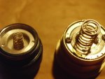
Only used the battery's in this build. These are button tops so the in series connect between the 2 is good.
Using a NiteCore D2 charger and all seems good.
I won't have a chance to check today.. BobM but curious to what you might see?
Using a NiteCore D2 charger and all seems good.
I won't have a chance to check today.. BobM but curious to what you might see?
Last edited:


")