Welcome to Laser Pointer Forums - discuss green laser pointers, blue laser pointers, and all types of lasers

LPF Donation via Stripe | LPF Donation - Other Methods

Links below open in new window

ArcticMyst Security by Avery

Planning DIY TPS63000 based driver

jib77

0
Joined
Jun 19, 2010
Messages
718
Points
0
Pretty cool! Yeah, looks good once soldered, very good job there!


I thought you knew you were going to need really small value resistors! That's why I told you that the idea of using a potentiometer in paralel with the sense resistor woudn't work at all, as there are no pots with such low values. I only have 0.1ohm ones on hand right now, and I'm gonna need 5 of them in paralel for my TPS63020 based driver to be able to get some decent current. I can't wait for having more things to order to make another big online order with more proper resistors.

WILLING TO SEE THOSE O'SCOPE PICS!

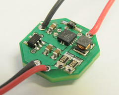
Thanks ... it cleaned up pretty good:
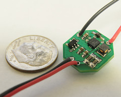


For scale:


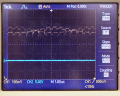
I knew they were going to be small, but not that small! I was thinking the gain was more like 3V not 20V(oooops). I ordered some 0.1Ω, 0.06Ω, and the last of the 0.075Ω current sense resistors. Here are the O-Scope pics ... but I forgot to scope the bench supply by itself to see how much of this is the supplies fault (cheap Chinese thing my boss bought in the Philippines):

Startup spikes mostly due to crappy supply switch:


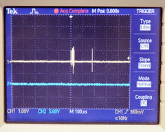
Shutdown spikes, again due to supply switch:
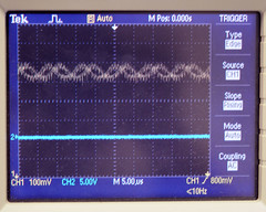

Ripple:


Last edited:


Rafa

0
Joined
Feb 4, 2010
Messages
437
Points
0
Oh man that driver looks PROFFESIONAL!!

Awesome. Thats the word, awesome.

BTW what's your job?
 
Joined
Jun 30, 2008
Messages
286
Points
0
I can see 100mVpp 100Khz ripple there. According to TPS63000 datasheet's captures, the frequency of the ripple is about the same they get, so that might come from the regulator itself, and not from the INA193 part. So yeah, pretty good specs! Maybe a bit of extra capacitance in the output would decrease the ripple, but looks like a good driver as is! And it surely looks professional!

Any capture of current ripple readings?

BTW I can't understand why your boss bought a crappy chinese PSU and also a quite pro Tektronics O-scope. It's a pain in the ass to combine good tools with crappy tools...
 

jib77

0
Joined
Jun 19, 2010
Messages
718
Points
0
Oh man that driver looks PROFFESIONAL!!

Awesome. Thats the word, awesome.

BTW what's your job?

Mostly I'm an embedded programmer ... Currently working on our own custom CycloneIII FPGA board and Chipcon CC1110 Radio Board. The FPGA is running a NIOS2 softcore processor w/ uClinux. It is interfaced with the CC1110 which has a slightly modified built in 8051 MCU. But I sometimes have to do schematic work (Mentor Design Capture), a little Verilog, and fix/modify our custom boards. So Ive picked up an eclectic mix of experience.

Any capture of current ripple readings?

BTW I can't understand why your boss bought a crappy chinese PSU and also a quite pro Tektronics O-scope. It's a pain in the ass to combine good tools with crappy tools...

Never done that before, how would I set up the scope to read current ripple?

Not sure, he is like that, sometimes he gets good expensive stuff, sometimes he doesn't. Can be really frustrating at times. Im just glad he gave me permission to buy a really nice Hakko dual soldering station ... its made my life a lot easier.
 
Joined
Jun 30, 2008
Messages
286
Points
0
Never done that before, how would I set up the scope to read current ripple?

Not sure, he is like that, sometimes he gets good expensive stuff, sometimes he doesn't. Can be really frustrating at times. Im just glad he gave me permission to buy a really nice Hakko dual soldering station ... its made my life a lot easier.

Hmm... I guess the optimal method for measuring currents would be some sort of current probe for the o-scope. Some look like a current clamp like those they use for measuring kiloamps on thick wires, but in miniature. I know they exist but i think i haven't seen any IRL.

What I do for current measurings is using a test load (some diodes or a power white LED) in series with a low value resistor, and I measure the voltage drop in the resistor. The same you do for adjusting current in an adjustable driver, but instead of using a DMM i use the o-scope.
 

jib77

0
Joined
Jun 19, 2010
Messages
718
Points
0
Thanks ... Ill try that.

BTW I got another running at 417mA w/ the 0.06Ω resistor. :)
 

jib77

0
Joined
Jun 19, 2010
Messages
718
Points
0
Interesting observation ... at 417 mA its stable but the temp of the TI IC was 235ºF ... yikes!

I tried 625mA and its having trouble stabilizing from a fully charged 16340 cell, at 833 it doesn't even turn on.

No enough input current?

This is the input diode ... its rated for 1A continuous:
>>Link<<
 
Last edited:

Rafa

0
Joined
Feb 4, 2010
Messages
437
Points
0
Interesting observation ... at 417 mA its stable but the temp of the TI IC was 235ºF ... yikes!

I tried 625mA and its having trouble stabilizing from a fully charged 16340 cell, at 833 it doesn't even turn on.

No enough input current?

This is the input diode ... its rated for 1A continuous:
>>Link<<

Lol, it's not the driver, now get some serious business 18650's and try again.:crackup:

It's been said many times on the forum that CR123A don't give high currents, even being lithium.
 

jib77

0
Joined
Jun 19, 2010
Messages
718
Points
0
I tried the bench psu which is 2Amps and it wont event put out any current ... the displays stays at [0.00A 0.00V]. I unhook the board+load and it goes back to [0.00A 3.70V]. This is both at 625 and 833 settings :(
Ill try bypassing the input diode on monday ... if the supplies needs more than 1A of continuous current it may be causing problems.
 

Rafa

0
Joined
Feb 4, 2010
Messages
437
Points
0
Swithcing drivers need a current spike when turning on, the diode might be the problem.

Thats a problem with crappy flashlights with crappy switches, the current spike does not pass thru the switch, so the laser does not turn on.
 

jib77

0
Joined
Jun 19, 2010
Messages
718
Points
0
Well I got bored again (uh oh). Here is the same design without the input diode with a more "traditional" shape:

3822-v3-top.png


3823-v3-bot.png
 
Last edited:
Joined
Aug 6, 2010
Messages
382
Points
0
Very nice looking project. With micro rc we tend to build "dead bug" style and eliminate the PCB due to excess weight.
I've been doing a lot of reading here and with boost drivers oscillators this probably wont work "dead bug". To much leakage and feedback issues.
 

Rafa

0
Joined
Feb 4, 2010
Messages
437
Points
0
Heya!
Don't you remember Erdabyz told you to keep the resistor current sensing traces as thin and as symetric as possible?
Probably the ripple is because you didn't done that in the other design, so...
 
Joined
Jun 30, 2008
Messages
286
Points
0
No, it's not a problem about current, li-ions can give 2 or 3 amps without effort, even CR123's , it's probably a problem about the diode.
It's TERRIBLY underrrated. It should be at least 2A continuous.

I don't understand why you add that input diode, i hadn't seen if before. If it's for protection then it should be better placed in an anti-paralel configuration, where it won't affect the input.

What is wrong about that diode is first that it's terribly underrated. You're probably getting very close to 1A under normal operation, and you're surely surpassing it trying to get to 833mA's. Being a low power diode means it's small and that normally means more Vf. It's probably dropping near 0.5V of the input voltage under normal load conditions. That means reducing the overall efficiency of the driver by around 5 to 20% and that means it's wasting more power, thus generating more heat.

Another thing is that when this drivers start from a low Vin, they usually like making quite scary transients with current spikes up to around 3x nominal input current. Those transients are nanoseconds long, but if the diode drops voltage and limits current, the driver might not even want to start.
While working with 1cell configs it's important to keep current paths as free of obstacles as possible. And with that diode you're increasing the magnitude and at the same time limiting the startup transient....

Dunno why I hadn't noticed it in the schematic...


EDIT: CRAP, SCHOTTKY DIODE DETECTED! EDITING SOMETHING IN MY POST.
 
Last edited:

gillza

0
Joined
Jul 26, 2010
Messages
583
Points
28
Can we expect something like Flexdrive replacement soon :) ?
 

jib77

0
Joined
Jun 19, 2010
Messages
718
Points
0
If I sell anything it will be the PCB. If ...
1) I can resolve the heat and stability issues at higher currents
2) you are willing to so some fairly advanced soldering


Top