Welcome to Laser Pointer Forums - discuss green laser pointers, blue laser pointers, and all types of lasers

LPF Donation via Stripe | LPF Donation - Other Methods

Links below open in new window

ArcticMyst Security by Avery

New test load

Joined
Aug 30, 2008
Messages
6,891
Points
83
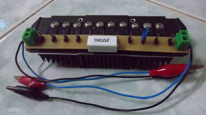
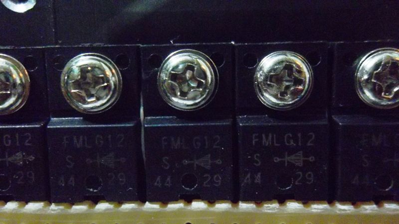
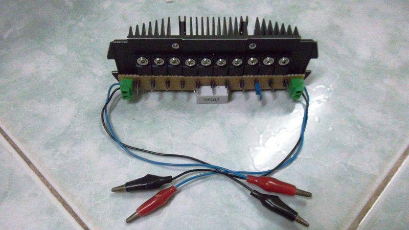
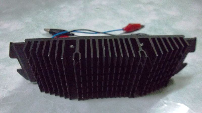
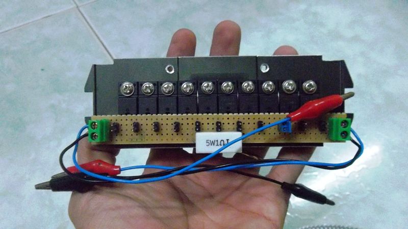
Just a picture of something in the works. This is before the copper bar is added to the diodes for heat sinking.
Has a 1, and 0.1 ohm resistor for measuring which is selectable and can be used to reduce the voltage drop over the resistor at higher currents.

Load voltage pads allow you to easily measure the total voltage drop. This was Benmwv's idea & the board was designed by him.
loads.jpg


Blord

0
Joined
Dec 24, 2007
Messages
5,356
Points
0
Very nice ! How much voltage drop is for each diode ?
 
Joined
Aug 30, 2008
Messages
6,891
Points
83
They're rated for .7v

DTR will be posting all the info once I get the remaining parts in and mail one to him.

As of now, I've only tested them with 1.25A which ran perfectly fine with no heat sinking. We'll see how they do with higher currents when the copper bar is attached.
 
Last edited:
Joined
Sep 12, 2007
Messages
9,399
Points
113
You should really use a bigger sense resistor. If you run them near their max rating, they heat up a LOT and cause erratic readings. It will cause the current to appear to rise with time, even though it isn't.
 
Joined
Aug 30, 2008
Messages
6,891
Points
83
Originals were 4527 sized smd resistors.

Ben said,
"I went ahead and changed the resistors to 2512 since those bigger ones are hardly in stock and they are expensive. Since you can select between 1 and 0.1 the lower power rating won't make much difference, and there is plenty of copper area to absorb the heat. I also added a simple way to test the total test load voltage."

So far, it hasn't been an issure. I still have to test the higher currents though. These boards do absorb heat really well. The entire back side is copper poured and the resistors and each diode has multiple vias holes leading to the back.

If it ends up being problematic, I'll probably switch to bigger resistors, or maybe some in a dpak package. I normally just go with ben's suggestions on those kinds of things though as I don't have the knowledge or experience with designing circuits.
 

benmwv

0
Joined
Sep 10, 2010
Messages
1,380
Points
48
Looks really small compared to that quarter!

There shouldn't be any problems with the resistor heating up and readings shifting, that's what the 0.1 ohm resistor is for. If you are measuring anything over maybe 1 amp use the 0.1 ohm resistor to cut down the power dissipation. If you want to run 2 amps through it that is 0.1 * 2 * 2 = 0.4W, easily handled by that 2512 resistor and big copper pads.

I'd say on the 0.1 ohm resistor and with the diodes heatsinked it will handle at least 3A, and maybe even up to 5A (not for very long though). 5A would be 2.5W on the resistor and 4W-5W on each diode!
 
Joined
Sep 12, 2007
Messages
9,399
Points
113
You're both missing the point entirely, I'm afraid. It's not about whether it will melt (that calculation is easy to make), it's about how accurate the reading is.

The resistance of a resistor increases at it heats up. If you send a lot of power to it, it heats up and the resistance slowly increases. With a constant current through it, the voltage drop across the resistor will increase as it heats up. The current appears to climb. This is a false reading.

Of course a 1W resistor running at 0.4W won't melt, but it won't be very accurate either. The 0.1 ohm is fine, but people tend to get confused by anything besides one-to-one :p
 
Joined
Feb 23, 2012
Messages
1,282
Points
0
Neat board!

Are there any datasheets on the 1 Ohm SMD resistors?
 

Blord

0
Joined
Dec 24, 2007
Messages
5,356
Points
0
I think that testload is futureproof. The new 510nm diode has much higher Vf than the already high 405nm diodes. The testload could be used for drivers powering these diodes.
 
Joined
Sep 20, 2008
Messages
17,622
Points
113
I gotta agree with Cyp on this one... Those resistors
seem way too small to stay in resistive specs..

Size is not the point on a Test Load...
You aren't going to shove it into an Aixiz module...

It is way easier to passively dissipate heat off larger
surfaces.


@tomsk...

now that's the size of a Test Load I like to see...
After all it is a piece of test equipment... :gj:
The extra diodes won't hurt a bit and you're
ready for the future in case you need it..


Jerry

You can contact us at any time on our Website: J.BAUER Electronics
 
Last edited:

tomsk

0
Joined
Jan 26, 2010
Messages
88
Points
18
Thank lasersbee,

This is the final finishing.Resistor 1 Om/5W not make me happy when you want to check one driver in the long run.It runs quite hot due to the heat sink, and I had to replace the 5W to 10W at the same time put it on the radiator, very good meet all requirements.

SAM_0947.jpg
 

benmwv

0
Joined
Sep 10, 2010
Messages
1,380
Points
48
First test load that uses a 0.1 ohm resistor to significantly cut down heat and keep readings from drifting. Gets flamed by people saying the readings will drift.

:thinking:

Do you guys realize all other commercial test loads use 1 ohm resistors? I only know of one with a heatsink. Others claim they can handle 2-3A (4-9W!) with a radial or ceramic resistor like the one in Tomsk's load. We put 0.4W through a 2-3W resistor (with big copper pads and will be sold with the board heatsinked) and that's too much.

I guarantee this test load will be more accurate than one using a ceramic 5W 1ohm resistor. Pump 2 or 3A though that and then try to tell me ours will get too hot :crackup:
 
Joined
Sep 20, 2008
Messages
17,622
Points
113
First test load that uses a 0.1 ohm resistor to significantly cut down heat and keep readings from drifting. Gets flamed by people saying the readings will drift.

:thinking:

Do you guys realize all other commercial test loads use 1 ohm resistors? I only know of one with a heatsink. Others claim they can handle 2-3A (4-9W!) with a radial or ceramic resistor like the one in Tomsk's load. We put 0.4W through a 2-3W resistor (with big copper pads and will be sold with the board heatsinked) and that's too much.

I guarantee this test load will be more accurate than one using a ceramic 5W 1ohm resistor. Pump 2 or 3A though that and then try to tell me ours will get too hot :crackup:

Man.... you are way too defensive... We are trying to help
you in stating the resistors seem a bit small...

Who the He!! is Flaming you... take a step back and take a
breath...

I use a 25W 1 Ohm resistor on my test load... and .1 Ohm
10Watts resistors on other current related projects...

You are free to use whatever you want...


Jerry

You can contact us at any time on our Website: J.BAUER Electronics
 
Last edited:
Joined
Sep 12, 2007
Messages
9,399
Points
113
I prefer a >99.9% accurate reading by using an ammeter and getting rid of the resistor entirely, myself.


Top