Hiemal
0
- Joined
- Dec 27, 2011
- Messages
- 1,443
- Points
- 63
http://www.fairchildsemi.com/ds/FA/FAN4603.pdf
I stumbled upon this today.
Me and RHD were having a discussion if this IC would be viable or not, as the voltage "appears" to be fixed according to the datasheet....
However, based off of other IC's I've seen in the same category,(specifically this one; http://www.fairchildsemi.com/ds/FA/FAN5350.pdf) each different voltage output has to do with what the voltage reference is on the inside of the chip. If you want 1.87 volts output, then the voltage reference inside is 1.87 volts.
For example, if I took the ever reliable LM317, and took its adjust pin and without ANY external components, just attached it to the Vout pin, I would get 1.25 volts out. Simple enough. If I changed that internal voltage reference to 1.8 volts, I'd get 1.8 volts out.
Basically, that's the same exact thing they're doing with the IC listed above, though the neat thing about it is it has ALL the components necessary inside of the module already. It's a truly monolithic switching regulator. The only two things external that are needed are a Current sense resistor, and a capacitor.
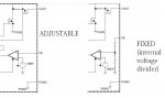
However, RHD seems to believe the IC has an internal voltage divider, making the FB pin useless... I really don't believe this is the case, as why would they even bother to put the FB pin in place then? It doesn't make sense. So I think they just change the internal voltage reference inside of the chip to alter the output voltage! If we got the 1 volt reference version, then the dropout of the regulator would be only 1 volt. And fairchild even states in the datasheet "Other voltage outputs available upon request" which may mean we can get some even lower versions if we ask nicely!
Which is why I believe this IC would be a perfect choice for the Open Source Buck version of the switching drivers we've started to create. Yes, the output current is limited to 600 mA for ONE driver. Since these things are so damn tiny, it would be trivial to add another driver to the same board and get even more current out.
6 volts input limit you say? Well, this driver fills in the gap for red laser diodes. The boost driver is great for driving blues, and violets; however, it can't drive reds though!
What are your thoughts?
I stumbled upon this today.
Me and RHD were having a discussion if this IC would be viable or not, as the voltage "appears" to be fixed according to the datasheet....
However, based off of other IC's I've seen in the same category,(specifically this one; http://www.fairchildsemi.com/ds/FA/FAN5350.pdf) each different voltage output has to do with what the voltage reference is on the inside of the chip. If you want 1.87 volts output, then the voltage reference inside is 1.87 volts.
For example, if I took the ever reliable LM317, and took its adjust pin and without ANY external components, just attached it to the Vout pin, I would get 1.25 volts out. Simple enough. If I changed that internal voltage reference to 1.8 volts, I'd get 1.8 volts out.
Basically, that's the same exact thing they're doing with the IC listed above, though the neat thing about it is it has ALL the components necessary inside of the module already. It's a truly monolithic switching regulator. The only two things external that are needed are a Current sense resistor, and a capacitor.
However, RHD seems to believe the IC has an internal voltage divider, making the FB pin useless... I really don't believe this is the case, as why would they even bother to put the FB pin in place then? It doesn't make sense. So I think they just change the internal voltage reference inside of the chip to alter the output voltage! If we got the 1 volt reference version, then the dropout of the regulator would be only 1 volt. And fairchild even states in the datasheet "Other voltage outputs available upon request" which may mean we can get some even lower versions if we ask nicely!
Which is why I believe this IC would be a perfect choice for the Open Source Buck version of the switching drivers we've started to create. Yes, the output current is limited to 600 mA for ONE driver. Since these things are so damn tiny, it would be trivial to add another driver to the same board and get even more current out.
6 volts input limit you say? Well, this driver fills in the gap for red laser diodes. The boost driver is great for driving blues, and violets; however, it can't drive reds though!
What are your thoughts?


 :beer: good luck