Welcome to Laser Pointer Forums - discuss green laser pointers, blue laser pointers, and all types of lasers

LPF Donation via Stripe | LPF Donation - Other Methods

Links below open in new window

ArcticMyst Security by Avery

NejTech Evolution - a new BOOST driver - Nearly finished!

Johnyz

0
Joined
Jul 19, 2010
Messages
421
Points
0
Just wanted to share what I'm currently up to with you guys. Since there is an awful shortage of boost drivers currently, china LED drivers are getting crappier and crappier, I decided it's time to dig up some of my plans from back when we were discussing the linear SimpleDrive. I originally dug up three IC's. Two from Linear Technology and one from National. LT IC's are even capable of buck-boost, but need so many external components and complicated board: one is 16 pin, other is 20 pin. Yuck! Let's see what National has to offer. 5 pins and minimal components! :drool: I won't be telling the IC names now, if you're that much curious try finding out yourself. Shouldn't be too hard. So anyway, right now, I'm about to order boards, there is still some space for layout improvement. I'll be posting info in this thread as I progress. Now it's time for some 3D renders! (Actual version as of 19.8.2011)

17.8.: Boards and parts arrived, and got soldered up. With a very highly sophisticated heatsink consisting of some Fujik glue and a screw, they are capable of supplying 1.2A from a 4.07V 18650.
25.8.: My 1 ohm 10w resistor just arrived. Did some more testing, it looks like high current = less efficiency, so I guess that I will set the max at 1A.
16.9.: Just threw together my OVP prototypes. From a 4V 18650 they give about 1A, and survive being ran without a load. Adjustable boards ordered.
4.10.: Kay... Seems we are officially adjustable! ATM the range is 1A-800mA; it seems I will have to sell different versions OR have solder jumpers... We'll see. Will post photos soon.

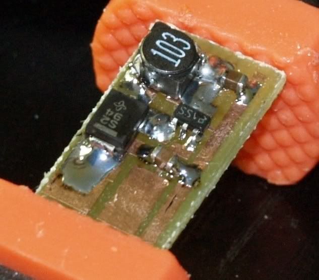
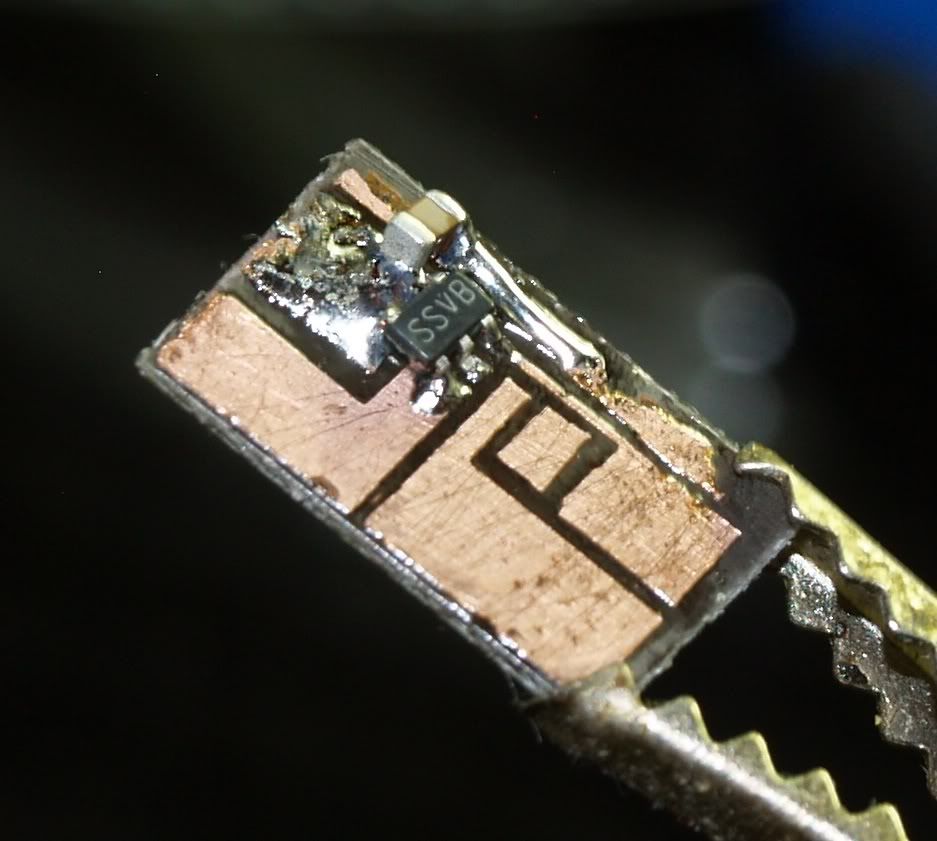
Actual working prototype and blank boards:


...firing at 1.195A from a 18650!


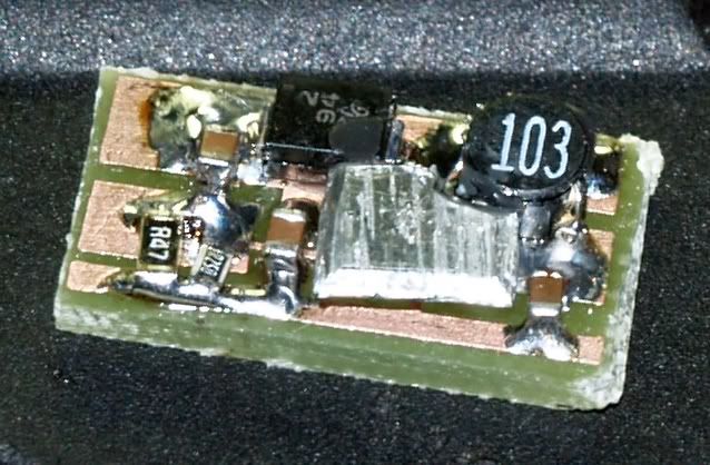
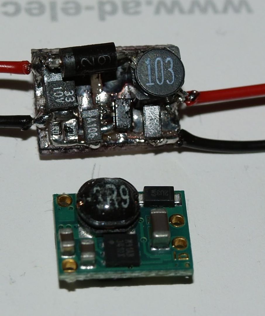
Results of testing with various inductors - I broke the casing on one, heh.

I have had best results with the inductor on the left so far. I also have one more to test, but I ran out of boards...


3D renders of new OVP version:


Uploaded with ImageShack.us
 
Last edited:


Joined
Jan 14, 2011
Messages
3,816
Points
63
Re: NejTech Evolution - a new BOOST driver - preparing to build prototypes

Interesting! How efficient is it? Input max/min? Output max/min?

AND WHERE IS THE INDUCTOR? :O
 
Joined
Feb 5, 2008
Messages
6,252
Points
83
Re: NejTech Evolution - a new BOOST driver - preparing to build prototypes

That wouldn't happen to be LM3410 or something derivated from it? :D From the board, it would appear to be connected exactly as thosse LM3410X I am working with for longer time now. If it is, you need another capacitor, directly parralel to the diode, not only schottky+diode.

Here are some of mine single-side boards:
Incomplete:
P5220327.jpg


Complete:
P5220334.jpg


Some older stuff...
P1290225.jpg


This one I'm proud of, only 1 mm larger than Flex:
P8040278.jpg

Yet, provided enough current for 8x BR diode, forgot which one was it now.
 
Joined
Oct 26, 2007
Messages
5,438
Points
83
Re: NejTech Evolution - a new BOOST driver - preparing to build prototypes

That's pretty cool, but you may consider doing your best to fit everything on one side. It helps keep the ground-plane solid, and then you can easy-bake-oven reflow it so you don't need to go about soldering these things up by hand (unless you're going through some shop). It makes it a bit easier if you want to sell volumes of these.
 
Joined
Feb 5, 2008
Messages
6,252
Points
83
Re: NejTech Evolution - a new BOOST driver - preparing to build prototypes

Or, if possible, have all the heat-critical components on one side (main IC, schottky, resistors) and the rest (three capacitors, or more depending on how you do it, and coil) on the other, for much easier heatsinking if you already have the professional setup for manufacturing high quality dual sided PCBs.

Heatsinking of criticals will increase efficiency of entire circuit by fair degree. You all know how much impact does that make in usefulness of these things in our handheld, and usually cramped-up hosts.
 
Joined
Mar 26, 2010
Messages
3,220
Points
0
Re: NejTech Evolution - a new BOOST driver - preparing to build prototypes

Ok, this is a pet peeve of mine.. How about you people hold off on these announcements until you actually at least have a working prototype? heh. At least Eudaimonium has physical proof his isn't just vaporware.

Just bugs me because 90% of these 'announcements' never really materialize.
 

Johnyz

0
Joined
Jul 19, 2010
Messages
421
Points
0
Re: NejTech Evolution - a new BOOST driver - preparing to build prototypes

Wolfman: See, the IC is labeled MAGIC, and needs no inductors! :na: Actually, it's right next to the schottky, it didn't get rendered. I'd have to calculate the exact efficiency using some complex math from the datasheet, but according to existing graphs it's gonna be over 85%. Input is from about 2.5V up to 5.5V.

Eudaimonium: :whistle: There's surely a lot of space for layout improvement, thanks for the tips. About the IC, well, I was looking at some designs from LT, but these were overly complicated, so I returned to this IC. Also, the caps ARE there, right next to the schottky. Some really clean hand made PCB you got there!

qumefox: Don't worry, I'm about to do real prototypes soon.
 
Joined
Dec 17, 2010
Messages
1,144
Points
48
Re: NejTech Evolution - a new BOOST driver - preparing to build prototypes

Anxiously waiting....:pop:
 

Johnyz

0
Joined
Jul 19, 2010
Messages
421
Points
0
Re: NejTech Evolution - a new BOOST driver - preparing to build prototypes

Just finished my "little" redesign, the PCB got actually a LOT shorter. I could even make a dimmable version in future. The IC peaks in efficiency at between 3.5V and 4.5V which is IDEAL for us.

EDIT: just replaced the Schottky from SMB to a smaller form factor. It's now less than 9mm in width!
 
Last edited:
Joined
Feb 5, 2008
Messages
6,252
Points
83
Re: NejTech Evolution - a new BOOST driver - preparing to build prototypes

@qumefox, it's definetly not vaporware, I've made around 15 of those so far. They are all working great. But, I do not intent to mass produce and sell those. Primarily because they are all handmade, not exactly selling-level of manufacturing process quality.

@Johnny, About the capacitors. Not sure what IC is the one you're using but you most definetly need to consider this. In the LM3410 referrence datasheet schematic (common usage one), you've got input capacitance and output capacitance. Now, I've spoken to IgorT a while back and he says that the schematic is not fully complete. The output capacitance on the schematic is known as "schottky capacitance" between us, coloqially.
You need a real output capacitor, which is parallel only to the laser diode, not LD+ schottky diode as you have it.

Here, refer to this expertly modified schematic in MS paint done in 3 seconds by, yours truly ( :D ):
driverboost.jpg
 

Johnyz

0
Joined
Jul 19, 2010
Messages
421
Points
0
Re: NejTech Evolution - a new BOOST driver - preparing to build prototypes

Yep, the new version I just posted renders of has the third LD cap. With the new schottky, the driver is now narrower than 9mm. I should look into placing the power contacts a bit better, that could save us a mm too.
 
Joined
Dec 17, 2010
Messages
1,144
Points
48
Re: NejTech Evolution - a new BOOST driver - preparing to build prototypes

Yep, the new version I just posted renders of has the third LD cap. With the new schottky, the driver is now narrower than 9mm. I should look into placing the power contacts a bit better, that could save us a mm too.

Sweet. This would be a welcome micro driver addition to the lineup. :) dimmable, too? Great!
 
Joined
Sep 20, 2008
Messages
17,622
Points
113
Re: NejTech Evolution - a new BOOST driver - preparing to build prototypes

@qumefox, it's definetly not vaporware, I've made around 15 of those so far. They are all working great. But, I do not intent to mass produce and sell those. Primarily because they are all handmade, not exactly selling-level of manufacturing process quality.

Hey Eud....
I think you read qumefox's post wrong...
He said that YOURS was NOT vaporware because you had
built and tested yours...

@ qumefox...

I agree.... too many times when a member has a "eureka"
moment they post of this great new find and all the units
they will sell in the future... without any field testing.
I generally try to design.... build and test something up to
and beyond specs before I announce our "eureka" new
whatchamacallit...
This give us some credibility when we put out a product..

@ Johnyz....

Keep up with your Boost Driver project and really test is
up to destruction... That's the only way you can be sure
of the specs you will hang on your Driver..


Jerry
 
Last edited:
Joined
Feb 5, 2008
Messages
6,252
Points
83
Re: NejTech Evolution - a new BOOST driver - preparing to build prototypes

I know, Jerry I was just saying that's it's working and results of testing should not be doubted, only the testing itself taking place.

If Johnny goes mass producing these, that'll be great!

Though, one thing is troubling me. You have placed two 2.7 ohm in parralel to achieve 1.4A output ... LM3410 has 190mV of reference voltage and 1.35 ohm will result in 0.14 A, not 1.4A > Are you sure you're not mistaking here?

If this is some sort of 3410 derivate, you need 0.135 ohms, not 1.35 ohms.

Then again, maybe it's something totally else.

EDIT -

Oh one more thing, @ Johnny

Them damned capacitors :D My LM3410 circuit requires me to use somewhere around 10 uF input cap, at least 10uF "schottky+LD" capacitance, and output capacitance at least twice as much as schottky+LD one.
If you take a closer look at the second picture I posted up there, "completed" one, at the left there is output to diode and you can see that there are two capacitors one on top of eachother. And yes I know that sounds very wrong. :p

Again I do not know what IC you're using, but make sure you have enough capacitance to hold voltage and current through out the pulsing cycles of the switching process. If you don't, you can destroy both the driver and diode.
 
Last edited:
Joined
Mar 26, 2010
Messages
3,220
Points
0
Re: NejTech Evolution - a new BOOST driver - preparing to build prototypes

My comment was directed at Johnyz, not you Eudaimonium. (btw, you need a shorter, less hard to type when half asleep name. :D )
 

Johnyz

0
Joined
Jul 19, 2010
Messages
421
Points
0
Re: NejTech Evolution - a new BOOST driver - preparing to build prototypes

Though, one thing is troubling me. You have placed two 2.7 ohm in parralel to achieve 1.4A output ... LM3410 has 190mV of reference voltage and 1.35 ohm will result in 0.14 A, not 1.4A > Are you sure you're not mistaking here?

If this is some sort of 3410 derivate, you need 0.135 ohms, not 1.35 ohms.

Then again, maybe it's something totally else.

EDIT -

Oh one more thing, @ Johnny

Them damned capacitors :D My LM3410 circuit requires me to use somewhere around 10 uF input cap, at least 10uF "schottky+LD" capacitance, and output capacitance at least twice as much as schottky+LD one.
If you take a closer look at the second picture I posted up there, "completed" one, at the left there is output to diode and you can see that there are two capacitors one on top of eachother. And yes I know that sounds very wrong. :p

Again I do not know what IC you're using, but make sure you have enough capacitance to hold voltage and current through out the pulsing cycles of the switching process. If you don't, you can destroy both the driver and diode.

They actually are 0.27 ohm, it's just Eagle3D not rendering it correctly. Thanks for the capacitance tip.
EDIT: Darn, 22uF is the biggest 0603 cap I can get... might need to switch to 0805 for some caps.
 
Last edited:


Top