Welcome to Laser Pointer Forums - discuss green laser pointers, blue laser pointers, and all types of lasers

LPF Donation via Stripe | LPF Donation - Other Methods

Links below open in new window

ArcticMyst Security by Avery

Micro Boost Driver Calibration help

ncm

0
Joined
Mar 16, 2012
Messages
4
Points
0
I am currently trying to build a 405 laser pointer I have a

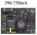
Micro BoostDrive DC/DC Converter Portable Laser Driver
Ultrafire 14650 battery

I am yet to order the diode or the lens. I wanted to make sure I could calibrate the driver properly before spending a good portion of money on a diode.
Thus we come to the problem. I hooked up the driver to a test load of six lN4001 diodes and a 1 Ohom resistor in series to my driver. The driver is set to 390-750 mA. When I attach the 14650 battery the reading I obtain across my load resistor is 20-40 mA depending on where the pot is turned to.

Any suggestion as to why my output current is low. I'm sorry I cannot supply any pictures I do not have a camera that would be able to take a picture worth posting.

Thank you for any suggestions you may be able to offer.


AnthoT

0
Joined
Jan 14, 2012
Messages
2,133
Points
48
There are some set resistors in the back and you must solder a bridge corresponding to the output you want. Make sure you do a good job soldering that as those are tiny resistors that could easily come off with your soldering iron. Check the boost drive datasheet for the correct solder bridge
Hope I could help :)

And I see it's your first post too so,
Welcome to the forum enjoy your stay, learn something new and be safe :beer:

-Anthony
 

DTR

0
Joined
Jun 24, 2010
Messages
5,684
Points
113
You won't need to solder on the smaller resisitors as the previous post suggested for that range. It is a really easy one. There is one large resistor on the back and a contact area next to it. Bridge it with solder according to the yellow line in this picture.;)

hacyloncaseeduebaylaser.png
 
Last edited:

AnthoT

0
Joined
Jan 14, 2012
Messages
2,133
Points
48
You won't need to solder on the smaller resisitors as the previous post suggested for that range. It is a really easy one. There is one large resistor on the back and a contact area next to it. Bridge it with solder according to the yellow line in this picture.;)

hacyloncaseeduebaylaser.png

I'm not too familiar with that driver so you should take DTR's suggestion. Sorry for giving you the wrong info..... Thanks for correcting me :beer: now I know


-Anthony
 

ncm

0
Joined
Mar 16, 2012
Messages
4
Points
0
I have soldered the bottom resistor shown in your post and yet it is still only giving me a range of 20-40 mA. Thank you for the suggestion DTR and AnthoT.
 

DTR

0
Joined
Jun 24, 2010
Messages
5,684
Points
113
I have soldered the bottom resistor shown in your post and yet it is still only giving me a range of 20-40 mA. Thank you for the suggestion DTR and AnthoT.

It could be the test load but that sounds like it is still in the first mode. You are sure the solder bridge is making good contact?
 

ncm

0
Joined
Mar 16, 2012
Messages
4
Points
0
It seems to be a good connection but I will try to borrow a camera tomorrow so I may post some pictures of both the test load and the driver, Thank you again.
 
Last edited:

ncm

0
Joined
Mar 16, 2012
Messages
4
Points
0
With a closer inspection using a magnifier one of the resistors was shorted to ground with a small speck of solder causing the micro boost driver to look as though it was in the first mode. Thank you again for all your help


Top