benmwv
0
- Joined
- Sep 10, 2010
- Messages
- 1,380
- Points
- 48
Hey guys, rhd's magic board and IRON4D driver will be at cajun lasers very soon so I am writing a little tutorial of how to use them.
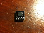
First up is the magic board. For those of you who dont know, this is a small circuit rhd made that allows you to put your battery in backwards and the laser (or flashlight, or anything else) will still work. It isn't just reverse polarity protection, it allows it to function with the battery inserted either way.

These boards are about 10mm x 10mm. The max input voltage is 20v, or no more than 4 li-ion cells (5 cells 21v maybe at your own risk). Minimum voltage is about 2.5V. These drop very little voltage, about 0.06v per amp (0.08v max). If you are going to run more than 3 amps through it you should consider heat sinking it though. At 3 amps thats about 0.5W, and at 5A thats about 1.5W of heat on the board. I'd recommend to stay under 3A, 5A absolute max (with heatsink), but with good heatsinking it is possible you might get away with more.
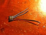
It is very simply to use, just solder on wires like so:

The two pads labeled "IN" (blue wires) are your non-polarity-specific inputs. Connect these to your contact board. The two pads labeled "+" and "-" (red and black wires) are the positive and negative outputs. Connect the to your driver. It is important to note that this board will not work unless the diode and driver are isolated from the host. So case positive or case negative diodes will have to be isolated. You can still use the case to get your positive or negative feed though. You just have to make sure the only electrical connection with the case is one of the "IN" pads on the magic board, and everything after that comes from it's + and - outputs.
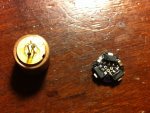
Now the IRON4D. This is a tiny amc7135 driver that sits directly on the diode pins. It's like 11mm round I think, it will fit behind the module in a heatsink but it doesn't fit inside an aixis module back barrel. There will be 700ma and 1050ma versions at cajunlasers. Works with one li-ion cell only. The max input is 6v and the minimum is about 0.3v + diodes Vf. This driver is meant for the mits 635nm diodes. One driver for the 300mw version, and you can stack two for the 500mw version. It can also work for other low voltage diodes but you will have to figure out how to do it yourself because the pinout will be different. The diode has to have fresh, unsoldered pins to fit this driver properly.
I didnt have any 5.6 diodes with fresh pins to waste, but I did have some 9mm IR diodes with nice long pins. I put one in a 9mm module just a bit, I wanted it to come back out easy.

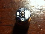
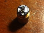
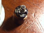
First step is to put the driver on the diode pins. They line right up and it is made for mits 635nm diodes so you cant mess it up. Rhd even gave us a nice message on the driver to make it entirely foolproof.

Now solder it on and clip your pins.

At this point you have two choices. You can solder on a wire for the positive lead to go to a contact board:

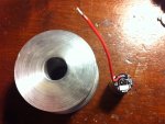
Or you can solder on a spring: (make sure the spring is big enough that it doesn't touch the didoe pins)

In both cases the negative feed comes through the diode case pin so you only need one wire (or spring). Even if you have stacked two drivers you only need one connected, it will share with the other through the diode pins. If your host is isolated, or you chose to isolate the diode you can solder a wire to the tiny pad the says "GND" for your negative input. If you want to use this driver with a magic board you will have to clip off the case pin of the diode before you solder on the driver and wrap the driver in tape so it is isolated from the host. Then run the negative output of the magic to the gnd pad of the IRON4D.
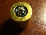
Now you are done and you can stick it in a heatsink. These drivers are great for making modular lasers. The tabs of the AMC7135's will probably touch the heatsink wall but that doesnt matter because they are already connected to ground. If you are using a case positive host or a magic board you will need to isolate it like above.

First up is the magic board. For those of you who dont know, this is a small circuit rhd made that allows you to put your battery in backwards and the laser (or flashlight, or anything else) will still work. It isn't just reverse polarity protection, it allows it to function with the battery inserted either way.
These boards are about 10mm x 10mm. The max input voltage is 20v, or no more than 4 li-ion cells (5 cells 21v maybe at your own risk). Minimum voltage is about 2.5V. These drop very little voltage, about 0.06v per amp (0.08v max). If you are going to run more than 3 amps through it you should consider heat sinking it though. At 3 amps thats about 0.5W, and at 5A thats about 1.5W of heat on the board. I'd recommend to stay under 3A, 5A absolute max (with heatsink), but with good heatsinking it is possible you might get away with more.
It is very simply to use, just solder on wires like so:
The two pads labeled "IN" (blue wires) are your non-polarity-specific inputs. Connect these to your contact board. The two pads labeled "+" and "-" (red and black wires) are the positive and negative outputs. Connect the to your driver. It is important to note that this board will not work unless the diode and driver are isolated from the host. So case positive or case negative diodes will have to be isolated. You can still use the case to get your positive or negative feed though. You just have to make sure the only electrical connection with the case is one of the "IN" pads on the magic board, and everything after that comes from it's + and - outputs.
Now the IRON4D. This is a tiny amc7135 driver that sits directly on the diode pins. It's like 11mm round I think, it will fit behind the module in a heatsink but it doesn't fit inside an aixis module back barrel. There will be 700ma and 1050ma versions at cajunlasers. Works with one li-ion cell only. The max input is 6v and the minimum is about 0.3v + diodes Vf. This driver is meant for the mits 635nm diodes. One driver for the 300mw version, and you can stack two for the 500mw version. It can also work for other low voltage diodes but you will have to figure out how to do it yourself because the pinout will be different. The diode has to have fresh, unsoldered pins to fit this driver properly.
I didnt have any 5.6 diodes with fresh pins to waste, but I did have some 9mm IR diodes with nice long pins. I put one in a 9mm module just a bit, I wanted it to come back out easy.
First step is to put the driver on the diode pins. They line right up and it is made for mits 635nm diodes so you cant mess it up. Rhd even gave us a nice message on the driver to make it entirely foolproof.
Now solder it on and clip your pins.
At this point you have two choices. You can solder on a wire for the positive lead to go to a contact board:
Or you can solder on a spring: (make sure the spring is big enough that it doesn't touch the didoe pins)
In both cases the negative feed comes through the diode case pin so you only need one wire (or spring). Even if you have stacked two drivers you only need one connected, it will share with the other through the diode pins. If your host is isolated, or you chose to isolate the diode you can solder a wire to the tiny pad the says "GND" for your negative input. If you want to use this driver with a magic board you will have to clip off the case pin of the diode before you solder on the driver and wrap the driver in tape so it is isolated from the host. Then run the negative output of the magic to the gnd pad of the IRON4D.
Now you are done and you can stick it in a heatsink. These drivers are great for making modular lasers. The tabs of the AMC7135's will probably touch the heatsink wall but that doesnt matter because they are already connected to ground. If you are using a case positive host or a magic board you will need to isolate it like above.